This thread has been locked.

If you have a related question, please click the "Ask a related question" button in the top right corner. The newly created question will be automatically linked to this question.

SE555: Start up Sequence Question

Part Number: SE555

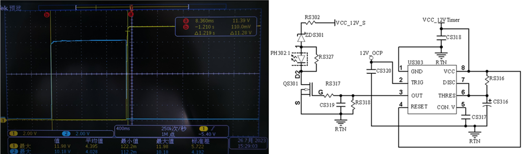
We have defect sample from production line. For the defect unit, the OUT will pull high first than VCC. The duration time is around 1.2s. But the good unit is VCC going first than OUT, and the duration is around 250mS.

This application is already production and no see other issue. I want to do the FA analysis, but need confirm you fist. May I know you have any recommend? thx

BR, Gary

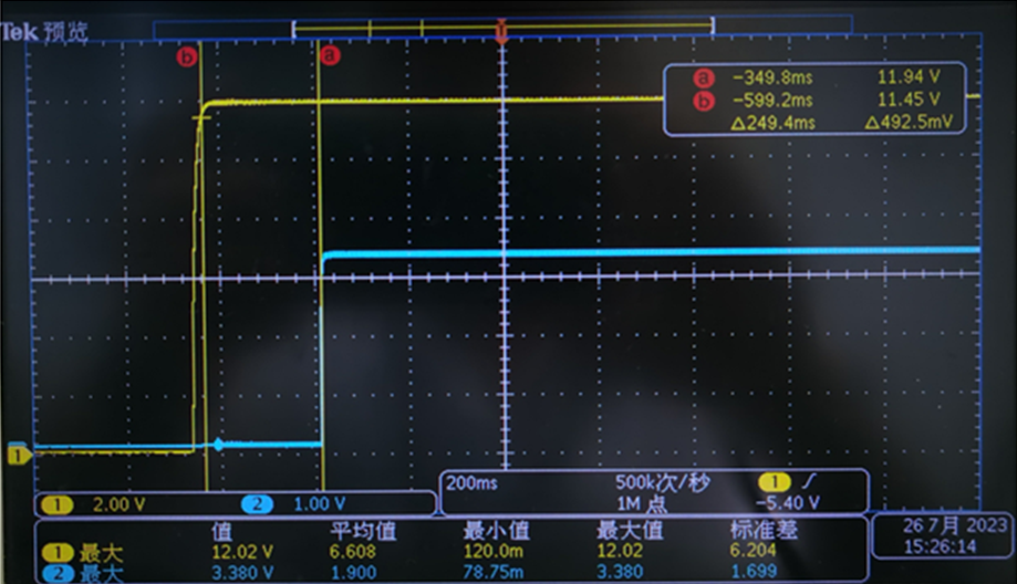
CHI: Pin-8 VCC, CH2: Pin-3 OUT

Fail Unit:

CS316: 100uF

RS316: 10k

CS317: 10nF

Good unit:

  • Hey Gary, 

    The output of the timer cannot go above the supply rail without it being forced by something else in the circuit. If the supply is 0 V as shown in the scope capture the timer itself will not output a value of anything above the supply. This means that something else in the circuit/conditions is forcing the output pin high. The output appears to have been forced to approximately 10 V above the supply. This has the potential to compromise or damage the device. 

    Has the output of the timer been disconnected from the gate of the transistor in order to isolate the problem?

    Has the device been replaced during the debug process?

    If transients are suspected to cause overvoltage conditions, circuit protection is advised such as TVS diodes on the output of the timer to the supply. Please reference our electrical overstress series here:

    https://www.ti.com/video/series/precision-labs/ti-precision-labs-op-amps.html

    Best Regards, 

    Chris Featherstone

  • Hi Chris,

    Thanks for your support.

    I think the external circuit is no problem because I change a good IC then the problem is solved. 

  • Gary, 

    The trigger pin appears to be supplied by a separate 12 V supply that is different than the power supply to the part. What level is the trigger pin voltage during power up? If any of the pins are exceeding the supply during power up it is likely the abs max condition is being violated and therefore damaging the device.  

    Do you have any measurements on any other pin that are approximately 10 V that could be pulling up the output of the timer? 

    Best Regards, 

    Chris Featherstone

  • Hi Featherstone,

    We checked the Trig is 10.5V, and the VCC is also less than 12V.

    CH1: Pin2, CH2: Pin3, CH3: Pin4, CH4: Pin5

    Regards,

    Gary

  • Gary,

    I believe the unit that was shown in the first scope capture at the top of this post is damaged and not defective. Let me know if I can be of further assistance. 

    Best Regards, 

    Chris Featherstone