Because of the Thanksgiving holiday in the U.S., TI E2E™ design support forum responses may be delayed from November 25 through December 2. Thank you for your patience.

This thread has been locked.

If you have a related question, please click the "Ask a related question" button in the top right corner. The newly created question will be automatically linked to this question.

CDCE62002: lowering spurs levels

Part Number: CDCE62002

Hi,

we are using cdce62002, for converting ref clock of 13MHz to a clock of 204.8MHz.

below is the configuration we are using.

the issue is that we are facing many spurs at the output (please see attached screenshot of spectrum analyzer). these are quite low, but not low enough for our application...
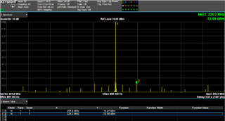
my question: can you recomned of other confguration which can lower the levels of these spurs?  or make them at higher offsets from carrier (i.e. move them away so we can filter out uisng bandpass filter)

thanks

Dan

Fin = 13MHz
REFSEL/AUXSEL = AUX:
Reference Divider = 1:
Input Divider = 13:
FeedBack Divider = 512 and Bypass Divider = 2:
Loop Filter Select = 1:
VCO = VCO2:
Lock Detect Window = 2.1ns:
Prescaler = 2:
Output Divider = 5:
  • also here is the ini file created by the GUI currently:

    REGISTERS
    0 72A800A0
    1 803F6191
    2 00000002

    PORTS
    0 DD
    1 FF
    2 DF
    3 F9

    INPUTS
    PRI 13
    AUX 13

    EXTERNAL COMPONENTS
    C4 1
    R4 1
    C5 1

  • Dan,

    Are these spurs present on the input as well, or solely from the device? If the spurs are the input as well, you can reduce the PLL bandwidth (the GUI will recommend components for different loop bandwidths).

    You can also modify the charge pump current. There is a tradeoff between the level of the spurs and the PLL noise in this case. A larger charge pump current may reduce PLL noise but increase spurs, and a smaller value may reduce spurs but increase PLL noise.
    Thanks,

    Kadeem

  • these spurs are solely from the device.

    regarding the charge pump current: as far as I remember, we tried many settings of the current, and still haven't gotten lower levels.

    I posted the register we are using now. is it possible that you load them into a device in your side, and try achieving better spur levels?

    thanks!

  • Dan,

    I will investigate this and get a response to you by Friday (PST). I have connected the board with the same setup in our lab, and also see the spurs at ~-74 to -76 dB with your configuration.


    Thanks,
    Kadeem

  • great, looking forwards to it

  • Dan,

    I have tested numerous combinations of frequency plans and both internal and external loop filters. There is very little difference in the magnitude and position of the spurs between any of these changes (although some face more difficulty locking than others).

    Thanks,

    Kadeem

  • and if I told you I am only concerned about spurs with offset up to 20MHz from carrier? I would like them to be -90dBc and below...

    could you find a better configuration?

  • Dan,

    The results that I was looking at were only for 15 MHz offset from the carrier (our instrument only captures up to 15 MHz away with centering on the carrier, otherwise the center frequency must be changed).

    None of the configurations of loop filter and PLL settings yielded sufficient spur reduction, especially not below -90dBc.

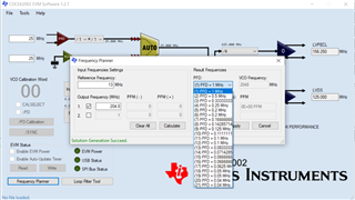
    For additional testing on your side, you can use the built-in frequency planner, enter the reference and output frequencies, click "Calculate", then for the PFD select one of the 21 possible options:

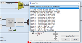
    Once selecting a PFD setting, the loop filter can be modified using 4 fully-internal settings or multiple external settings, changing the C3 & R3 values:


    Thanks,

    Kadeem