This thread has been locked.

If you have a related question, please click the "Ask a related question" button in the top right corner. The newly created question will be automatically linked to this question.

LMK61E2-100M00EVM: The output clock has problem

Part Number: LMK61E2-100M00EVM
Other Parts Discussed in Thread: LMK61E2, LMK61E0M, LMK6C

Hi,

I hope that you are doing well.

I have problem with module LMK61E2-100M00EVM.

I would like to understand what is the problem with the output clock?

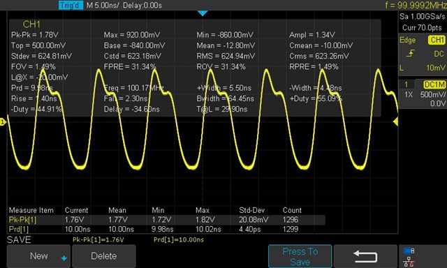
Normally, it should be LVPECL format, but it is not and it is not in good shape too.

Thank you in advance for your reply.

Best regards.
  • Hi Thanh, 

    To help assist you, can you confirm a few details about your test setup:

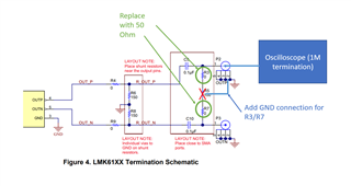
    1. Are you using the default LVPECL termination scheme that is on the EVM? 

    2. Is this measurement using a high impedance probe, or is there a 50 Ohm termination from the scope? An additional 50 Ohm termination can result in different amplitude measurements compared to what the datasheet specifies 

    3. Are both OUTP and OUTN connected to the scope? Signal integrity may be worse if only one of them is connected due to a load mismatch on the output driver of the LMK61E2.

    Regards, 

    Connor 

  • Hi Connor,

    1. Yes

    2. I use coaxial cable to connect from the module to the scope

    3. I only connect OUTN to the scope

    In fact, I use this clock to active an ADC DC782A-T www.analog.com/.../dc782a-t.html.

    However, there is a lot of noise at the output of ADC.

    How to solve this issue?

    Thank you in advance for your advice.

    Best regards.

  • Hi Thanh, 

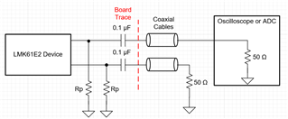
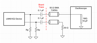
    Since the ADC only has 1 clock input with a 50 Ohm termination, I would recommend terminating the unused output from the LMK61E2 with a 50 Ohm load so both OUTP and OUTN have the same termination. Here's a simple schematic as an example:

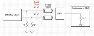
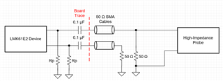
    Note that Rp and the 0.1 uF caps should already be populated on the EVM. Another option is to use a balun to convert the differential signal to single-ended and connect it directly to the scope or ADC like this:

    Let me know if this helps improve the waveform on the scope or the noise from the ADC. 

    Regards, 

    Connor 

  • Hi Connor,

    Thank you for your advice.

    I have tried the first schematic, I have connected a 50ohm resistor on OUTP.

    However, I have gottent the same issue on the scope.

    And it still has noise when I try to apply the clock to my ADC.

    Could you please help?

    Thank you so much.

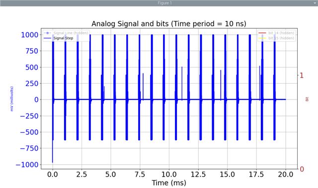
    Here is the periodic noise on the output of my ADC.

  • Hi Thanh, 

    Sorry for the delayed response, I tried out a LMK61E2 EVM (with the default AC-coupled LVPECL termination) in the lab and I saw a single-ended swing of around 900 mV and no problems with overshoot. This was on a scope with an internal 50 Ohm termination. Can you confirm if your scope has an internal 50 Ohm termination, or if it's set to high impedance? Also, are these measurements taken at start up or is this the steady state behavior?

    I've reached out to some other members on my team to discuss the noise on the ADC, I should be able to get back to you with some feedback about that in the next day or two.

    Regards,

    Connor

  • Hi Connor,

    Thank you for your reply.

    I think our scope is the 1Mohm // 16pF.

    And I take these measurements at the steady state.

    So what should I do?

    Thank you. 

  • Hi Thanh, 

    I think there's an issue with the signal integrity when you directly AC-couple the output into a high impedance load, and I'm seeing similar results on my end. When I use a high impedance input on the scope, the single-ended amplitude increases to around 1.3V. I would recommend probing across the 50 Ohm resistor that you added to OUTP, or even better would be at the 50 Ohm termination on the clock input of the board with the ADC. If that signal looks good, I think we can rule out any issues with the clock. 

    Regards, 

    Connor 

  • Hi Connor,

    Could you please show me the schema?

    I think the clock input of the ADC module, there has been a 50 ohm already.

    Thank you.

  • Hi Thanh, 

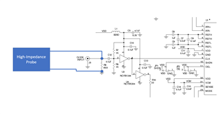
    Sorry for the confusion, just to confirm is this how you're measuring the clock signal on the scope when you see the waveform from your first post? 

    If so, this would explain why the signal isn't matching regular LVPECL levels. The best way to see what the clock output from the LMK61E2 will actually look like in the system is to measure the signal with a 50 Ohm load. This would usually be done with an internal termination on the oscilloscope, but since your scope has a 1M termination you can use a high impedance probe to measure across a 50 Ohm resistor to GND, like the R8 resistor on the ADC board.

    If you don't have a high impedance probe or can't make good contact with the probes around R8, another option is to add a 50 Ohm to GND resistor on the LMK61E2 EVM and use the same setup with the coaxial cable to 1M termination on the oscilloscope that you were using before


    Either one of these setups should show a clean clock signal with proper LVPECL levels. Let me know if this makes sense.

    Also, based on feedback from some other members in my team, they think it's more likely that the noise issues on the ADC are coming from the analog input or some other problem with the ADC configuration. It might also be worth reaching out to Analog Devices if you haven't already to double check the rest of the setup around their device. 

    Regards, 

    Connor 

  • Hi Connor,

    Thank you for your detail reply.

    I will try that tomorrow.

    However, for ADC, I believe that the noise comes from the clock.

    Because when I input a 10MHz clock from the agilent signal generator or a 50Mhz clock from Digital Digilent Dicovery, the ADC does not show any noise.

    I have already contacted ADC, they also told me that the noise is from the clock.

    Could you please help me check again about this issue.

    Thank you so much for your support.

    Best regards.

  • Hi Thanh, 

    Understood, in that case it would be ideal to probe across R8 on the ADC board with a high-impedance probe to make sure that the clock signal looks as expected. 

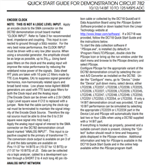
    I was double checking the ADC user guide and it looks like they recommend a large amplitude signal for the clock (2.5 V square wave into a 50 Ohm load): 

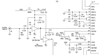
    The clock is also being used as an input to the NC7SVU04 buffer which requires the input to be 0.8 * VCC to meet the VIH requirements. R7 and R9 set the DC bias to 0.5 * VCC, so the signal swing needs to be at least 1.8V peak to peak assuming VCC = 3V. Would it be possible to switch to a LVCMOS oscillator? LMK61E0M or LMK6C could meet the swing requirements if R8 is removed. You could also try using a balun to convert the LVPECL output of the LMK61E2 single-ended and double the amplitude, and this would most likely give better jitter performance compared to an LVCMOS oscillator. 

    Regards, 

    Connor 

  • Hi Connor,

    Thank you so much.

    Could you please show me a balun module that I can use?

    Thank you in advance for your reply.

    Best regards.

  • Hi Thanh, 

    Some baluns that we use are the ZFSCJ-2-1+ and ZFSCJ-2-4+ from Minicircuits. If the swing still isn't large enough, I would recommend using an LVCMOS oscillator and removing the biasing network on the ADC EVM so the clock goes directly into the NC7SVU04 buffer. You should be able to drive it with a 2.5V or 3.3V LVCMOS signal.

    Also, in the final design you should be able to directly drive the CLK input of the ADC with the LVCMOS oscillator without any additional square wave conversion circuitry. I think the ADC EVM was designed this way because it assumes you will use a sine wave from a signal generator to provide the CLK input, but if you're using an LVCMOS clock source then I don't think it's necessary.

    Regards, 

    Connor 

  • Hi Connor,

    LVCMOS that you mean LMK61E0M and LMK6C?

    I have tried with this CMOS clock https://www.mikroe.com/clock-gen-click but it still has some errors like this.

    Normally, do I need to sync the clock between the DAQ and ADC?

    Thank you.

    Best regards.

  • Hi Thanh, 

    Correct, LMK61E0M or LMK6C would be the best device we have for an LVCMOS oscillator. LMK6C is a fixed-frequency part so it would be easier and cheaper to design in. LMK61E0M requires programming so it's a little more complicated but it would give more flexibility with choosing the output frequency. 

    I'm not sure if you need to sync the clock between the DAQ and ADC, you might need to reach out to Analog Devices about that. 

    Regards, 

    Connor