This thread has been locked.

If you have a related question, please click the "Ask a related question" button in the top right corner. The newly created question will be automatically linked to this question.

LMK00105: LMK00105 recommended crystal?

Part Number: LMK00105
Other Parts Discussed in Thread: LMK6C, CDCM6208

hello,

i have to update an board, some parts are eol. i am not the designer from the board, that is the reason why i check every ic and the passive components.

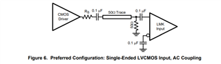
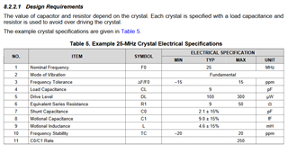
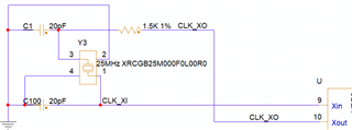
at the board is an LMK00105 with an XRCGB25M000F0L00R0 crystal. i check the lmk datasheet, and in my opinion the crystal is not recommended.

i am right? have somebody an recommended part for me?

thanks a lot

  • Hi, 

    That's correct, the device will most likely have better performance if an oscillator is used at the CLKin inputs instead of using a crystal and OSCin. Do you have any phase noise or jitter requirements for the LMK00105 outputs? 

    We have an LVCMOS oscillator called LMK6C which has a 25 MHz variant and it would be fairly straightforward to use following the configuration from Figure 6 in the LMK00105 datasheet. Let me know if you have any other questions. 

    Regards, 

    Connor 

  • Hello,

    sorry i think my question was not precise enough. i check the datasheet again. i thought the crystal specifaction are recommended but it is only an example.

    The lmk is used for an cylcone 5 hps clock and an CDCM6208 primary reference clock.

    i think i ve to check the datasheets more deeply

  • Hello,

    Much of the team is out of office through January 1st. Please expect a response by January 2nd.

    Thanks,

    Kadeem

  • Hi, 

    Sorry for the confusion, in that case section 8.2.2. and Table 5 of the datasheet can be used as a reference for choosing a crystal and termination network for the OSCin/OSCout pins. Usually the most important thing is to make sure the load capacitors (C1 and C2 as shown in Figure 19) are correctly matched to your crystal's specifications, otherwise the oscillator circuitry might not startup correctly. Let me know if you have any other questions. 

    Regards, 

    Connor 

  • hello,

    thanks for the answer.

    i check the load Capacitance from the XRCGB25M000F0L00R0 it is 6pf. But at the schematic the capacitors are 20pf. i think this is a lot to large, right?

  • Hello, 

    Agreed, that could be too much of a load for this crystal. From equation 3 of the LMK00105 datasheet, C1 = (CL - CIN - CSTRAY) * 2 where CIN is 1 pF and CSTRAY could be around 1-3 pF depending on your PCB traces. Based on this, C1 and C100 in your schematic should be around 4-8 pF. 

    Regards, 

    Connor