Hello everyone,
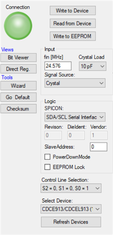
I am trying to generate 48kHz, 6.144MHz and 24.576MHz clocks using a 24.576MHz crystal and a CDCE913. I can program the device via I2C (all bytes are acknowledged), the crystal oscillates but all outputs (Y1, Y2, Y3) remain low. What could I have done wrong?
The schematic: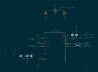
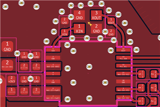
The Layout:
The Clock Pro configuration: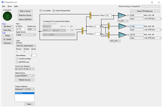
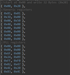
The text file:
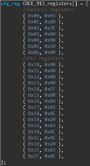
Bit ==> 76543210
Byte 00 - 00000001
Byte 01 - 00000000
Byte 02 - 00111110
Byte 03 - 00000000
Byte 04 - 00000000
Byte 05 - 01010000
Byte 06 - 01000000
Byte 07 - 00000000
Byte 08 - 00000000
Byte 09 - 00000000
Byte 10 - 00000000
Byte 11 - 00000000
Byte 12 - 00000000
Byte 13 - 00000000
Byte 14 - 00000000
Byte 15 - 00000000
Byte 16 - 00000000
Byte 17 - 00000000
Byte 18 - 00000000
Byte 19 - 00000000
Byte 20 - 11101111
Byte 21 - 00000000
Byte 22 - 00000100
Byte 23 - 00000001
Byte 24 - 01001110
Byte 25 - 00100000
Byte 26 - 10000011
Byte 27 - 01001100
Byte 28 - 01001110
Byte 29 - 00100000
Byte 30 - 10000011
Byte 31 - 01001100
The array: