This thread has been locked.

If you have a related question, please click the "Ask a related question" button in the top right corner. The newly created question will be automatically linked to this question.

CDCE906: Example Code

Part Number: CDCE906
Other Parts Discussed in Thread: CDCE913, CLOCKPRO

Hi,

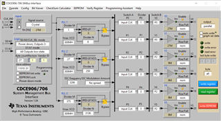
Do we have any demo code or example code we can share for setting up the CDCE906?  I want to configure its clock output via the I2C bus ,but I only have the chip connected to the MCU and no CDCE906-EVM

  • Also, there's something I don't understand after reading the datasheet:

    1.If I give a 27 MHz input, how do I configure the register to make Y0~Y1=27 MHz while Y2~Y5 = 9 MHz? Can Y0~Y5 output different values simultaneously?

    2.ClockPro Software has the bit viewer function.but only have the following devices which are available:CDCE913/925/937/949, If I want to configure CDCE906 registers , which model can I refer to?

  • Hello,

    TI Pro Clock must be used for writing configuration code for this device: https://www.ti.com/tool/download/SCAC073

    In this software, the CDCE906 can be selected and a configuration created.

    See below for an example:

    Once you have created a configuration, it can be exported as a .txt or .csv file in the "File" menu.

    Thanks,

    Kadeem

  • Hi,

    I've got some trouble, here's the situation:

    cdce-906 A0,A1 pin is floatted, So its address is 1101011(R/W),I tried to write a byte to cdce906 ,so CommandCode is 0x80, then I send a test code 0b00110101,here is a sequence diagram of the program.

    I think the program worked.

    Thus, I send all 'data[i]' configured in TI Pro Clock,I tried to write a block to change the output:start--address 1101011(0)--readask--command 0x00--readask--count 27(number of all registers)--readask--{data[i]--readask......}-readask-stop

    then I tested the output pin ,nothing changed.

    Is there anything wrong with the communication protocol I configured?Why is the output frequency still the default state?

  • Hello,

    The clock gen team is out of office until Tuesday 1/16. Please expect a delay in response and thank you for your patience.

  • Hello,

    Based on your capture, it seems that your starting sequence is incorrect. As seen in the image below, the start condition requires the SDA to be pulled LO, followed by the SCL being pulled LO. If you follow this protocol, does the communication succeed? 

    Best,

    Cris