Other Parts Discussed in Thread: CDCE6214
Dear TI support team,
I'm evaluating part CDCE913 to obtain two clock, one 20MHz and one 80MHz. Crystal is 16MHz, PLL freq is 160MHz, output frequency values are OK, used Y2 and Y3 output.
In the application the phase relationship of the two clock needs to be know, or set to a predefined value.
At the moment I'm not able to get this, phase looks random and not controllable, sometime is good, sometimes is not.
What I've tried to do:
- configure all register to get required frequency
- set Pdiv2 and Pdiv3 to zero ( reset and stand by )
- stop PLL ( PWDN = 1 )
- set Pdiv2 and Pdiv3 to 2 and 8 to get the correct frequency
- start PLL ( PWDN = 0 )
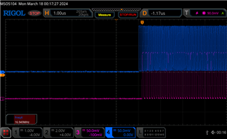
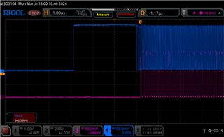
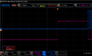
what I found is that when PLL restarts the two output restart from random values, and not always 0 as they should do ( at this point I'm assuming the have to start from value 0), like there is some sort of glitch happening.
after PLL lock time the two signal reach the desired frequency, but being the start condition undeterminable, then the phase is also not determinable.
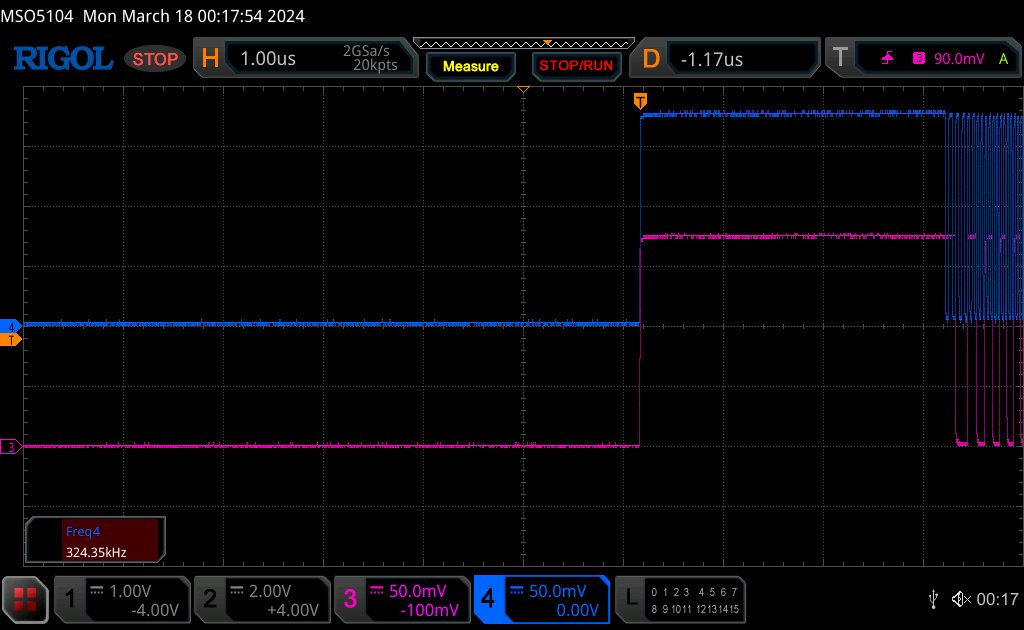
I have some oscilloscope capture to show:
expected behaviour, the two output restarts from 0

erroneous behaviour ( different glitches )


could you please advise on how to get a stable start up condition?
Best regards,
Antonio

