This thread has been locked.

If you have a related question, please click the "Ask a related question" button in the top right corner. The newly created question will be automatically linked to this question.

LMK04828: LMK04828 related issues

Part Number: LMK04828
Other Parts Discussed in Thread: LMK04832

Tool/software:

Hello,

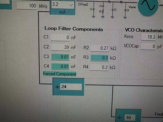
Question 1: What parameters do the Kvco and VCOCap in the picture represent when the customer uses the LMK04828 clock chip?

Question 2: The customer saw that the loop filtering parameters can be set to 2nd, 3rd, and 4th order filters. Are C3, C4, R3, and R4 corresponding to the 4th order loop filtering parameters in the figure? If that's the case, how do I set the internal loop filtering parameters of LMK04828?

Thanks!

  • Kvco is the gain (in MHz/V) of the tuning voltage of the VCO. So for example, a one-volt change of the tuning voltage, in the screenshot above, would result in a nominal deviation of about 18 MHz. This slope isn't perfectly linear and varies slightly with frequency. We provide it as an optional parameter to override in case of external VCO usage.

    VCOCap should represent the fixed capacitance (or equivalent capacitance) on the Vtune port. In the LMK04828, the Vtune port is integrated, so the VCOCap is equivalent to C4. Hence this value should be left at 0pF. It is worth pointing out that the charge pump port also has some parasitic capacitance due to the FETs used in the output stage, and this capacitance comes out to about 60pF; we typically represent this as part of C1. So even if you set C1 to 0nF on the hardware, in simulation you should restrict it to no less than 60pF to be representative of actual circuit behavior.

    C3/R3 and C4/R4 correspond to the third and fourth order components of the loop filter, respectively. Check the datasheet for descriptions of registers 0x16C and 0x16D for configurable options. In PLLatinum Sim, you can select the component to force using the "Restrict Components" window in "Smart force selected values" mode, all of which is located on the Filter Designer tab in advanced feature level. We generally don't recommend modifying these values since there's rarely a reason to - usually we just keep them present for debug in case of issues during silicon validation. You can certainly experiment with the settings, but there's typically not enough benefit to warrant the time spent experimenting. For reference, in LMK04832, the p2p-equivalent performance improvement variant of LMK04828, these loop filter component values are fixed and not user-configurable - we didn't see any value in exposing these settings when given the opportunity to revisit them in LMK04832.