This thread has been locked.

If you have a related question, please click the "Ask a related question" button in the top right corner. The newly created question will be automatically linked to this question.

LMK01010: Driving with LVCMOS

Part Number: LMK01010

Tool/software:

Hi,

I'll be driving LMK01010 directly with my XO with limited current capability and it'll also have to drive another load (~400 ohm) in parallel, so I cannot spare much current to drive the LMK01010.

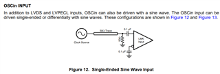
There is information in the datasheet on driving the part with an AC coupled sinewave. Can you please provide some information on how to drive the clock input with LVCMOS 3.3V?

Thanks,

Christer

  • Hello Christer,

    The same topology can be used for LVCMOS for the pin connected to the OSC. Just make sure the output impedance of the OSC is 50Ω. If it's not, make sure to add a series resistance close to the OSC. For the unused pin, make sure to tie it to the midpoint of the LVCMOS signal.

    Also, the LMK01010 has a high input impedance, so the current draw from the LMK01010 should be minimal to non-existent.

    Best,

    Andrea

  • Hi Andrea,

    Even if adding a 50-ohm series resistor followed by a 50-ohm shunt, that's 3.3/(50+50) = 33 mA, which is too high. The XO can only deliver 16 mA.

    If the single-ended input is high impedance, can you give me some information on:

    • Input resistance
    • Input capacitance
    • Maximum and recommended Vpp swing

    Thanks,

    Christer

  • Christer,

    The input driver of the LMK01010 is high impedance so your current budget should not be a concern with this part. Let me reach out to the design team and get back to you.

    Best,

    Andrea

  • Christer,

    The maximum operating conditions for the LMK01010 are:

    Here is the information on input impedance and Vpp recommendation:

    Link to E2E above.

    The input capacitance for CLKin1 is 1.151pF and for CLKin0 is 0.6pF.

    Best,

    Andrea