This thread has been locked.

If you have a related question, please click the "Ask a related question" button in the top right corner. The newly created question will be automatically linked to this question.

cdce62002 temperature problems

Other Parts Discussed in Thread: CDCE62002, CDCE62005

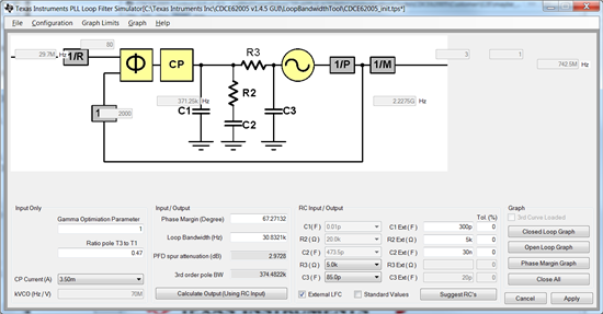
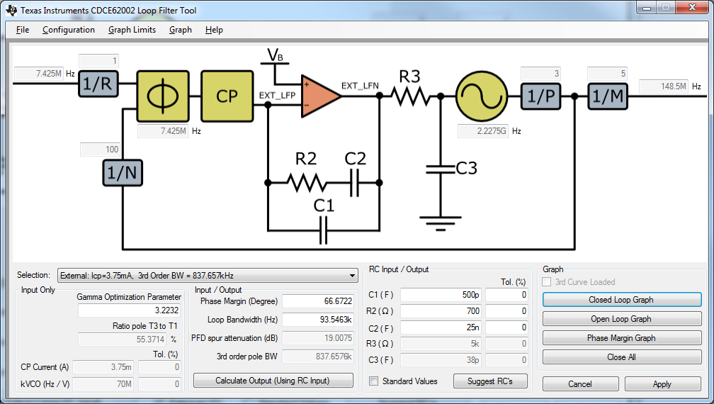
I am using the CDCE62002 to lock a HD video clock, output 74MHz, input 30MHz (approx).

From ambient, the CDCE comes up, and stabilises to acceptable jitter within 30 seconds.  After about 4 minutes, the jitter increases, and then the clock output becomes unstable enough not to lock a receiver.  After about another 2 minutes, the clocks stabilise and the jitter comes back to acceptable levels. After that, the clock output stays good all the time.  Adding heat (by an air heat gun) during the unstable period almost immediately gets the clock correct. Adding heat from the start shortens considerably  the early good period, and the bad period in the middle only happens for a couple of seconds.  This seems to indicate that at a particular temperature the chip becomes unstable.  Powering the chip down and up again when the chip is hot does not produce any problems.   Any comments of suggestions .. maybe this is a known issue..

  • Hi Martin,

    I suspect your loop filter settings are unstable. Please can you send me the register settings (or even better the ini-file for the GUI) and if you use an external loop filter please also send me the loop filter component values.

    Furthermore: You need to be sure that the input clock to the CDCM62002 is valid when the device calibrates. So if you power up from EEPROM, you need a valid clock at power up. If your software controls the calibration time, then you just need to be sure you issue the calibration sequence after the reference is stable and no longer drifts.


    Much thanks. BR. Falk Alicke

  • Hi Fritz,

    This may well be on the edge, as I have one unit which works all the time.

    The clock is being derived from a 54MHz VCXO, which is line locked to incoming video syncs, so there will be slight line-locked jitter between 15KHz and 33KHz, though this does not affect the way the CDCE falls out of lock.  The 54MHz is sent through a Xilinx DCM, to get the input frequency of 29.7MHz.  The input divider is set to 80, giving a PLL compare of 0.371MHz.  Prescalar is 3, feedback divide is 200, feedback bypass is 10.  This gives an oscillator frequency of 2227.5MHz - the relevant output clock is divide by 10, giving 74.25MHz.  I have had the loop filter external, with LFRCSEL set to all 1's, as this seems to give the best jitter.  The external loop components are C1=1nF, C2=100nF, R3=3K0.  Capacitors are 10%, resistor is 1%.

    The CDCE is stuffed after the input clock is stable, with the following data

    0x554000d0, 0xbcb9a9f1, 0x01021802, 0x00021802, 0x01021802

    The clock always comes up at the correct frequency and locks.

    Changing the LFRCSEL settings from 1111 to 0100 significantly increases the jitter below 10KHz to unacceptable levels, but does not cure the unlock problem.

    Internal filter components do not produce acceptable jitter, using 0000 gives unacceptable jitter at 10KHz and below.

    I can try any set of external and LFRCSEL settings, and measure the jitter both when the unit is locked to video syncs, and when it free runs with the VCXO set to a dc voltage. 

    I need to get the jitter at levels that look good - the serial output is 20x clock, at 1.485Gb/s.  I am using a Tek 7000 series analyser to look at the jitter, which has filters for 100KHz, 10KHz, 1KHz, 100Hz and 10Hz.  For 100KHz and 10KHz I am getting less than 0.12UI.  At 1KHz 0.34UI, at 100Hz 0.34UI, at 10Hz 0.60UI.  These are the values I am aiming for - the 1KHz and below jitter is mainly due to line locking, as the 10Hz setting with a free running oscillator is down to 0.30UI. 

    Many thanks

    Martin


  • Hi Martin,

    following questions/comments:

    Register 0: you show to write 0x554000d0; However, register bits 2 and 3 are supposed to be set to 0 as of D/S (reserved bits).

    Registers 3-7: you didn't provide any data. If I assume device defaults here, you would be selecting internal loop filter (though I believe you used external LPF). Please send me a snapshot of all 8 registers. Otherwise I am also missing the charge pump current.

    You reported R3=3k0. I assume you really meant R2=3k0

    It is important to set the R3 and C3 properly. I can only do so after I understand your loop bandwidth. THe device has an active loop filter. THerefore, you can set R3C3 such that 1/(2*pi*R3*C3) is 10x higher than your bandwidth. However, the loop filter tool as part of the GUI takes also care of this. Are you running the latest CDCE62005 GUI?

    http://e2e.ti.com/support/clocks/m/videos__files/353682.aspx

    The GUI will be able to calculate the BW. You want to be sure to achieve the following values if you keep the PFD frequency at 370kHz:

    BW < 37kHz (10x lower then PFD frequency)

    Phase margin between 45-80 (I like it right around 65).

    CP current: I recommend using something higher, maybe 2mA (1.5mA to 3.5mA). I would avoid 400uA personally, as a very small current could have the largest variation and any leackage current can impact overall stability.

    I recommend you use the following settings in your external LPF:

    C1=300pF

    R2=5k

    C2=30nF

    R3=5k

    C3=85pF

    Here a screen shot of the LPF tool insides the GUI

    Note: Gamma wasn't recalculated in the figure shown here. It's around 10 in reality.


    Now, here is the secret to much better jitter:

    Start out with a much higher PFD update rate to reduce the PFD spurs. Unless you have a particular reason, you shouldn't use such a low PFD frequency if you can avoid it. I recommend doing the following:

    Input divider=1

    Feedback divider = 20

    Prescaler=3

    output divider=8

    fVCO=1782

    fPFD=29.7MHz.

    Loop filter recommendation:

    C1=500pF

    R2=450

    C2=33nF

    R3=5k

    C3=8pF

    This should give you much better performance I suppose as the loop filter receives many more udpates. Your VCXO output I assume is very clean, so the high BW of approximately 250kHz will serve your system well.

    Please let me know how it went.

    Best regards, Fritz


  • Hi Fritz,

    I have altered the values of the R and Cs as in the first part of your reply, and the problem stayed the same, in that as things heat up, there is a period when the clock goes very jittery.  I then put the values in that are in the latter part of your mail, and got a much higher PFD - the reference divider is now 4, the feedback divider 100, the prescalar 3.  It's not possible to use a lower internal oscillator frequency, as I need 2 outputs, one of 74.25MHz (output div 10), and one of 92MHz (output div 8).  However, there is still a period of clock instability.  On the bench, the oscillator is stable, but applying hot air (or merely covering the board) produces a period of instability.  Once the chip is hot, I can then cool it, and see a period of instability on the cooling cycle.  I'm going to try and measure the case temperature when the clock goes unstable.

    The other thing I will do is to use the internal filter, and see whether then problem still occurs.

    I am using a CDCE62002, so your comments on registers 3-7 are not relevant.

    Martin

  • Hi Fritz,

    I have tested a little further, and the clock disturbance also happens on the internal filter.  I'll have to wait till tomorrow to measure the chip temperature, as the battery on my temperature probe is flat!.

    All the best

    Martin


  • Hi Martin,

    sorry, I realize now you are using the CDCE62002. The PLL architecture is the same and only he divider ranges vary a little so I guess we can still continue from the same point forward. I am surprised about this temp behavior. The CDCE62002 only calibrates after power up or when you initiate a CAL through SPI. It has no means to calibration on it's own. Therefore, I don't suspect the CDCE62002 but would consider a couple of other reasons. Here is what I recommend:

    1. Put a DC probe on the LPF loop filter input signal (EXT_LFN) using the external loop filter. After calibration, you should measure about mid-rail voltage going into the VCO. As temp increases or decreases, the control voltage will move some linearly to make up for the VCO resonant frequency change. However, as long as the control voltage stays with some headroom away from the GND and the VCC rail, you can be certian the device itself remails locked. So as long as you measure a good DC value, the jump you see must be something else. By the way, the device has lot's of temperature headroom, meaning even if someone calibrates at -40dC and ramps up to 85dC they should not see an unlock event. Your report about the device locking again after the temperature goes even higher makes me believe that this would certainly not be a headroom issue.

    2. Is it possible that your reference clock source causes the jump? See that you only heat up the CDCE2002, but not the reference.

    3. some customers have in the past reported piezo-effects with capacitors. What happens is that when a board expands or contracts with temperature, the capacitor becomes mechanically stressed, causing a sudden discharge through a piezo effect, which would cause such a phase jump. We have never seen this in our lab however. I only know some customers are very careful on the cap material they choose to avoid this.

    4. What signal do you have on the unused inputs? I have seen an issue in the past that the mux would pause for  a couple of input clock cycles if a customer had a clock turn on suddenly on AUX input (they used a CMOS clock on the AUX input). Is there any chance your secondary or AUX input sees some event? Can you bias each unused input such that the input will see static high or low? 

    5. Is it at all possible that there is a contact problem? Push on the device with your input finger - is there any change?

    6. Is the input signal biased correctly, terminated correctly and the input stage bits assigned correctly? If you let me know the signal swing that you measure on the input to the device, I can check if the registers look ok. It maybe that you have an insufficient input stage configuration, which will show up as input common mode threshold shifts slightly. I definitely have seen this in the past, if an input configuration was wrong. I think based on your config you use LVDS input with AC termination. I assume you give the input a differential signal, not single-ended, correct?

    Best regards. Fritz

  • Hi Fritz,

    I have done some more experiments, based on your suggestions.

    1] I have connected an oscilloscope to EXT_LFN.  On start  up from cold (ambient around 20C), EXT_LFN is around 0.8V.  This gradually rises at around 100mV per 10 seconds, and when it reaches around 1V,a few spikes of noise occur, and then the voltage goes totally noisy, going from rail to rail.  After 10-20 seconds, all goes quiet again, and the voltage gradually rises to 1.5V and stabilises.  It will now stay quiet, with low jitter.  Cooling down the chip makes the voltage reduce, until at around 1V all goes noisy again, and keeping cooling makes it quiet.  I have cooled the chip both with freezer, and also by applying a freezing bar of metal to just the top of the chip, and every time the noise occurs at the same voltage, in the same way.  Heating up the chip from above 1V does exactly what is expected, the EXT_LFN rises, but the chip stays locked and low jitter. Cooling or heating any of the other components in the system, i.e. the Xilinx and the master oscillator does not affect anything.  The acid test is the cold metal bar applied to just the CDCE62002, as this just cools that component.

    2] Heating and cooling the clock source makes no difference.

    3] Irrelevant, I think.

    4] I did have the AUX input (pin 2) open, but I have now grounded it - but that made no difference.  However, this is the source of the problem.!!!  Setting the Smart Mux bits (3 & 2 of register 0) to Auto (11) makes the clock instability occur, setting to Ref_In (01) makes the problem go away.  It would seem the the Smart Mux is not so "smart" - maybe you could look into this.  So, with Smart Mux set to Ref In, it seems no problems occur.

    5] No, pushing on the chip makes no difference.

    6] LVDS levels, dc about 1.7V., peak to peak 0.4V, balanced.  Terminating or ac/dc coupling makes no difference.

    So, I think that the problem is now solved, by setting the Smart Mux bits to Ref In.  However, I would be grateful if you could give me the ideal set of external components, based on an fPFD of 7.425MHz, and a oscillator frequency of 2227.5MHz, and specifying an R3, C3 and current combination that is in the CDCE62002.

    All the best

    Martin


  • Hi Martin,

    I am glad to hear the VCO stays locked now. Your observation actually makes sense. Here is what happened:

    The AUX input is internally AC coupled. The oscillator stage if no XTAL is connected will start to self-oscillate. Even if the external input is grounded, the AC coupling will still allow this internal oscillation. This oscillation only occured in a small temperature range. As soon as the AUX internally oscillates, the smart-mux has trouble because the oscillation frequency and the PRI-Input frequency differ by more than 10%, which is not acceptable by the spec.

    So by you selecting PRI input only, you practically disable the AUX stage, thus getting rid of the oscillation and the smartmux toggling.

    COncerning your question on the loop filter, and assuming a clean reference clock, I would use the highest possible bandwidth you can get, meaning to minimize R3 and C3. The smallest possible values are 5k and 38pF, with a I(CP)=3.75mA. This produces a 3rd pole at 837MHz. THerefore, your loop bandwidth should be equal or less than 100kHz. I recommend the following filter assuming fPFD=7.4MHz and fVCO=2.2GHz:

    C1=500pF

    R2=700

    C2=25nF

    R3=5k

    C3=38pF

    this will get you:

    BW=93k

    PM=99 degree

    gamma=3

    This should get you pretty good performance.


    Best regards, Fritz