Tool/software:
Tool/software:


Qingmei,
(1.2M Ω+10M Ω)
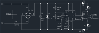
Where is the 1.2M ohm resistor? Can you turn off AC coupling on the output waveform. If output cycle time changes when a load is applied then I expect output current is high and gets back to the timing. Does that cause pin 8 & 4 to be too variable? How about the grounding, is waveform for pin 1, C3 bottom, C4 bottom the same? It should be useful to check waveforms for pins 5, 2+6 too.
Hello Ron Michallick
1、1.2M ohms at R3 position
2、Ac coupling off,
No load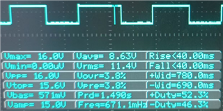
loading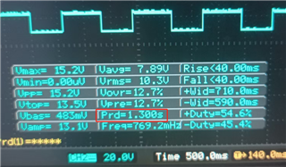
3、current13mA,
4、is waveform for pin 1, C3 bottom, C4 bottom same。
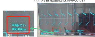
5、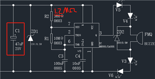 ,Why does C1 electrolytic capacitor affect the cycle
example:When C1 is not added, the cycle is 0.9s, and after adding C1, the cycle is 1.2s,Can you help me analyze why this is,thank you.
When C1 is not added, the cycle is 0.9s, and after adding C1, the cycle is 1.2s
For SA555, VCC voltage does not affect timing provided that VCC voltage is constant throughout out the timing cycle. With a [50/60 * 2] Hz signal on C1, VCC voltage will not be constant over a second and a half. This is even more true with C1 removed.
One way to make SA555 voltage more constant is to move RB1 to be between C1 and ZD1 and increases voltage rating of C1.
I see a timing glitch on no load waveform. Add a100nF cap close to SA555 power pins.