A related question is a question created from another question. When the related question is created, it will be automatically linked to the original question.
If you have a related question, please click the "Ask a related question" button in the top right corner. The newly created question will be automatically linked to this question.
For the LMK6H HCSL output, the traces should have a 100 Ohm differential impedance. If the traces aren't tightly coupled it's also ok to route each channel as 50 Ohm single-ended.
Thank you for your quick response. I was planning to only use 85 ohm differential impedance traces in my system. Will this have a large impact on the jitter performance?
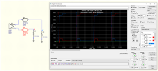
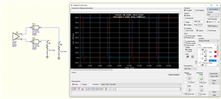
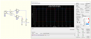
85 Ohm differential impedance is generally only used for LP-HCSL drivers, traditional HCSL usually uses 100 Ohm differential impedance since it's assumed that a 50 Ohm termination resistor will be used. If there is some impedance mismatch between the trace and termination, you'll see a reflection at the propagation delay of the trace for each rising/falling edge. So essentially, the longer the trace the worse performance you'll see. I've attached some IBIS simulation plots below, you can see in the cases where there's an impedance mismatch a reflection occurs at around 0.5ns after each rising/falling edge.
These reflections can be improved by adding a series resistor (usually 17-33 Ohms is common for HCSL drivers even with good impedance matching to help prevent overshoot/ringing), or by changing the termination resistor value. One downside with changing the termination value is that your amplitude will be affected since HCSL is a current-mode driver. For example, a 15mA output current will give 15mA * 50 Ohm = 750mV, but with a 42.5 Ohm termination the single-ended swing is reduced to 637.5mV.
Thank you for sharing these simulations! I am planning to have the output of the oscillator connect to the LMKDB1108 buffer so I believe even with the reduced swing, it's well within the acceptable limits.
I have three additional questions:
1. Does the driver itself have any sort of output impedance that you would want to match with the trace impedance and termination? Or is it just the termination and trace impedance that you need to worry about matching?
2. If the impedance is not well matched, does that affect jitter? Or just the voltage levels?
3. Can you please share a simulation where Z0 = 42.5 ohm, R = 42.5 ohm, and there's a series resistor on the outputs?
Got it, in that case if you're inputting into a universal receiver like LMKDB1108 there shouldn't be any issues.
1. HCSL output driver impedance is generally between 17 and 33 Ohms depending on the device. Essentially the driver is "oversized" to account for long traces, AC-coupling, different termination schemes, etc, and you can account for matching with a larger trace impedance by adding a series resistor.
2. In practice, most phase noise analyzers that are measuring jitter are sensitive to reflections as well as the amplitude. They track the timing of the edges of the signal, so any disturbance with reflections or reduced slew rate will negatively impact jitter. The amount of jitter degradation will depend on the exact layout of the PCB, so it's hard to generalize without taking actual lab measurements using the particular board in question.
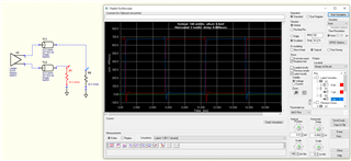
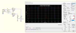
3. Simulation results are below, just note that the "ideal" value of 33 Ohms may be different depending on the parasitics and layout conditions of a real PCB. If you have layout files, I can import them into the simulation to get a more realistic idea of how adding a series resistor will impact the waveform.