This thread has been locked.

If you have a related question, please click the "Ask a related question" button in the top right corner. The newly created question will be automatically linked to this question.

LMX2582: Overshoot & Undershoot on SPI Lines

Part Number: LMX2582

Tool/software:

Hi ALL,

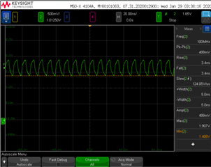
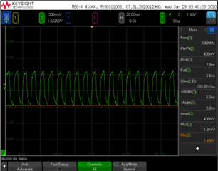
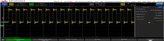
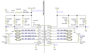
We’re using the LMX2582RHAT in our design, and we’re seeing some overshoot and undershoot on the SPI signals (CLK, CS, SDI). These signals are driven by an FPGA.

Here are the current drive strength settings:

  • PLL_SPI_EN: 12mA
  • PLL_SPI_CLK: 12 mA
  • PLL_SPI_MOSI: 12 mA

We’d like to know:

  1. is this overshoot & under shoot are within the acceptable limit?
  2. if not, can you please recommend how to reduce them

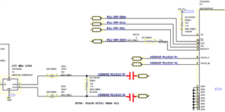
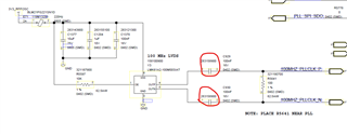
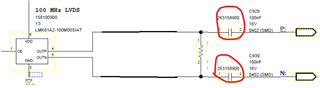
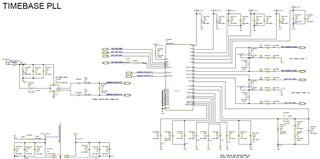
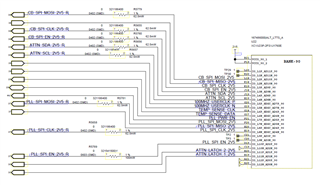
I’ve attached a signal capture of the SPI clock and the relevant schematic for reference.


Thanks

Sakthi

  • Hi Sakthi,

    You already have 0Ω series resistor in the SPI bus, you can simply change these resistors to 33Ω to reduce overshoot.

    OSCin of the LMX devices requires AC-couple, you need to add two more capacitors as shown below.

  • HI 
    in our design we placed the capacitor before the resistor ref des: C929, C930. we do not see any issue still in 100MHz clk. whether we need to move capacitor on another side of resistor.

    I have attached the image of design and wave form for your reference.

    '100MHZ_PLLCLK_P

    100MHZ_PLLCLK_N

    We changed the resistor value of the SEN pin. Instead of 0 ohm, we added a 33-ohm resistor, but it hasn't made much difference compared to 0 ohm. Do we need to adjust the drive strength of the FPGA?

  • Hi Sakthi,

    Your 100MHz source has LVDS output, it should DC-couple to the 100Ω load. 

    LMX device OSCin requires AC-couple, the capacitors should be placed in front of OSCin.

    The overshoot at SPI should not hurt the device, but you can increase the resistor value to reduce the overshoot, say 100Ω or higher.

  • Hi Noel,

    Sakthiraam is on leave and I am replying on behalf of him..

    We have a stable HW and intend to not do any PCB changes until critical.

    May I ask how crucial this suggested capacitor placement is since the waveform looks ok and PLL lock is happening consistently?

    Thanks

    Nandini

  • Hi Nandini,

    OSCin has internal bias, that's why we require AC-couple. 

    I checked the effect of the 100Ω resistor, if we place this resistor across the OSCin pins, the bias voltage changed a little bit, I would say it is safe to keep it there. However, if you have a chance to revise the pcb layout, please put the resistor before the AC-coupling capacitors.