A related question is a question created from another question. When the related question is created, it will be automatically linked to the original question.
If you have a related question, please click the "Ask a related question" button in the top right corner. The newly created question will be automatically linked to this question.
And there have few questions need your help. thanks!
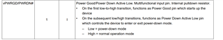
PWRGD/PWRDN# (Pin 1): Can this pin be always pulled down (PD)? Does PD indicate entering low power mode? If it can be always pulled down, can the pull-down resistor to ground be changed from 4.99kΩ to 10kΩ? What is the internal pull-down resistance?
LOS# (Pin 17): If not used, can this pin be left unconnected (NC)?
SMB_EN (Pin 15): To disable SMB mode, can the pull-down resistor to ground be changed from 4.99kΩ to 10kΩ? What is the internal pull-down resistance?
CLKIN_SEL_TRI (Pin 8): Can both the pull-up and pull-down resistors be changed from 4.99kΩ to 10kΩ?
CLK_N/P: In the reference design shown below, why are a 0Ω resistor in series and a 2pF capacitor to ground used? Is it for filtering purposes? Can the 2pF capacitor be replaced with a 2.2pF one?
Hello Jeff. 1. No PWRDN should actually be pulled high given its active low.
I would need to check with design as to what's the internal PD resistor value. 2. Yes, LOS can be left float if unused.
3. Yes, PD can be changed to 10k if needed. I would need to check with design regarding all internal PD values. They're all weak pull downs though. 4. Yes.
5. 0Ohm resistors give end user added flexibility and ability to AC couple if needed or also, account for any overshoot that might arise.
2.2pF is fine.
We go with 2pF as this is what the PCIe AC test load describes.
Regarding the response in point 5, we would like to confirm: is the purpose of the 2pF to GND simply to prevent overshoot from external signals? If we can ensure that the external signal is well-behaved, is it acceptable to remove this capacitor?