This thread has been locked.

If you have a related question, please click the "Ask a related question" button in the top right corner. The newly created question will be automatically linked to this question.

LMK5C33216A: Problem I2C communication with LMK5C33216A integration

Part Number: LMK5C33216A
Other Parts Discussed in Thread: LMK5C33216, LMK5C33216EVM, , USB2ANY, LMK00804B-Q1

Tool/software:

Hello,

I have integrated in my board a LMK5C33216ARGCR for synchronisation. I am testing the integration.
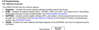
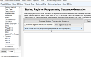
Once validated, I will put my configuration tested with EVK with TIcs pro software in the LMK5C33216ARGCR EEPROM of my design.

1) I set my design (by an FPGA) once powered

- GPIO0, GPIO2 to 3V3,
- GPIO 1 to 0V
- PD pin to 1V8
- VDD LMK power = 3,27V by using TPS62913RPUR.

2) I am using LMK5C33216 EVK for I2C communication.
I remove the jumpers (I2C/SPI INTERFACE) and I connect SCL/SDA (U2AGPIO0, U2AGPIO1JP5A) from LMK5C33216EVM to my design by with a wire.

I open TIcs pro software and I try to read registers.
I have " Begin reading back read only registers, Communication error Abording and read only registers Confirm Power is applied to device limited and PD# is High"

On my design, I cannot communicate by I2C with LMK5C33216ARGCR.

Questions :
Do you have an idee of the problem?
How can I debug?
What is the expective consumption of LMK5C33216ARGCR in a new design with PD # active or Not and power with 3V3?

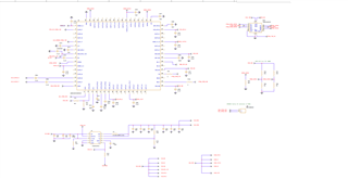
I have attached LMK5C33216A part schematic.

Thank you,

Regards,
Patrice

  • I check the power level 100

    GPio_Val.IO_SYNC_EN = 1;
    GPio_Val.IO_SYNC_GPIO0 = 1;
    GPio_Val.IO_SYNC_GPIO1 = 0;
    GPio_Val.IO_SYNC_GPIO2 = 1;

    - 0.7 W (PD =0)

    - 1 W (PD =1)

    Is it correct?

  • Hi Patrice,

    Please give me a few days to review. I will get back to you on Wednesday.

    Regards,
    Jennifer

  • Hello Jennifer,

    I managed to connect to my board via I2C. I did a scan and reduce the Bit rate with TICS Pro tools. I have device found address than I could read adresses. Thanks. Patrice

  • Hi Patrice,

    Thank you for the follow-up. Glad to hear you resolved it. We have observed this issue with the USB2ANY programmer before and are working on narrowing down the cause.

    Has the I2C error message shown up again after reducing the I2C rate?

    Regards,

    Jennifer

  • Hello Jennifer,

    I performed a bus scan in the communications configuration. The device was detected and the address was updated. Everything is OK now.
    I can configure the LMK5C33216A on my board (see schematic) by connecting the I2C pin of the LMK5C33216EVM.

    I'm testing my board, which includes an LMK5C33216A with a 40 MHz TCXO and an LMK00804B-Q1.
    I have an external 10 MHz signal connected to IN1_P (SMA_REF_IN1) and I'm trying to generate a synchronized 40 MHz signal on output 3 (LVDS, LVPECL).

    Output 3 of the LMK5C33216A (AD_CLOCK_N, AD_CLOCK_P) is connected to the output of the LMK00804B-Q1 (CLK_P / CLK_N).
    I expect the output of the LMK00804B-Q (Q1 to Q4) to be a CMOS clock (40 MHz) synchronized to the external 10 MHz clock.

    I opened a support question: "LMK5C33216EVM: LMK5C33216EVM: Synchronizing with an external 10 MHz sine wave."
    You provided me with the file e2e_XO=38.88MHz_REF=10MHz_OUT0=40MHz_sept232024.tcs.

    I successfully tested with the LMK5C33216EVM (OUT_0).

    I'm now trying with the LMK5C33216A, a TCXO = 40 MHz and OUT 3 (instead of the LMK5C33216, XO = 38.88 MHz, OUT0 = 40 MHz) synchronized to 10 MHz.


    If you have a TCS file, that would be very helpful.

    Thank you,
    Sincerely,

    Patrice

  • Hi Patrice,

    I remember now, yes, good thing you have switched to LMK5C33216A.

    Here is a tcs file you can test.

    e2e_LMK5C33216A_REF=10M_XO=40M_OUT3=40M_2025-07-09.tcs

    REF1 set to 10 MHz CMOS

    XO set to 40 MHz CMOS

    OUT3 set to 40 MHz HSDS VOD = 800 mV, VCM is 1 V.

    Please download the latest TICS Pro to use the LMK5C33216A profile. From there, you can make modifications by following the steps outlined in the "Start Page" page. Let me know if you have further questions.

    Regards,

    Jennifer

  • Hello Jennifer,

    Thank you for the tcs file. It works on my board, I can generate the CMOS 40 MHz at the outputs of the LMK00804B-Q1 from the LMK5C33216A.

    I will try to program the EEPROM of my board and thus have the configuration set up after power-on.

    I'm not sure if this is possible for the moment.

    Regards,

    Patrice

  • Hi Patrice,

    One thing to note is that the EEPROM does not store the DPLL registers which is needed to get the output to lock to the 10 MHz REF input. In-system programming will be required. More details on the datasheet sections: "8.4.4.3 Start-Up Options for Register Configuration" and "8.5.1 Memory Overview".

    My suggestion is to program the EEPROM which contains the majority of your register settings, then at boot-up, finish writing the missing DPLL registers through in-system programming.

    TICS Pro also provides post-EEPROM boot write sequence:

    Regards,

    Jennifer

  • Hello Jennifer,

    Thank you for your help, I succeed in programming the EEPROM.

    But, as the DPLL are not configured, I will configured LMK5C33216A by the FPGA once the module is power up and PD is released (I2C PS).

    From the .tcs, I have generated "start up programming sequence " (6 steps, 8.5.3 General Register Programming Sequence).

    I will follow the sequence by writting the value by I2C from FPGA.

    Regards,

    Patrice

  • Hi Patrice,

    The flow you mentioned above is valid, however, to speed up the boot time and reduce the number of register you have to write after power-up, I suggest doing as follows:

    1. Program EEPROM

    2. Boot-up

    3. Program registers listed in the "Post-EEPROM boot programming sequence (ROM only registers)". This sequence can be exported from the Programming page in TICS Pro.

    Regards,

    jennifer

  • Hello Jennifer,

    Thank you very much for your help. I followed your recommendations and everything is fine.

    The next step will be to configure the FPGA's registers (EEPROM post-boot programming sequence) to I2C instead of using I2C EVK with the TICS Pro tools.

    Thank you,

    Sincerely,

    Patrice