This thread has been locked.

If you have a related question, please click the "Ask a related question" button in the top right corner. The newly created question will be automatically linked to this question.

PLLATINUMSIM-SW: Invalid input frequency.

Part Number: PLLATINUMSIM-SW
Other Parts Discussed in Thread: LMK03318, LMK04826

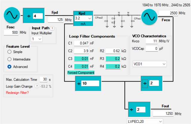
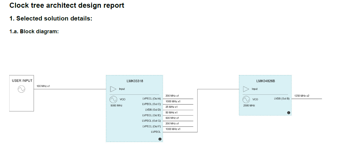
I used the Clock Tree Architect to come up with the parts for my clock tree. It has a LMK03318 sending a 1000 MHz signal to a LMK04826B. I went to PLLatinum Sim and selected the LMK033118 and got it setup to output a 1000 MHz signal. I then selected the LMK04826B with the cascade button checked and PLL2 with external VCO. I can adjust the dividers and what not to get my desired 1250 MHz output signal but the 1000 MHz input is marked in correct (red). I am not sure if this is an issue with the Clock Tree Architect or the PLLatinum sim. The data sheet for the LMK04826B says that you can have an input of up to 3100 MHz on the Fin pins, so it seems like maybe it is in the PLLatinum sim.
clock tree.png

  • Hi Joe,

    To use the PLL2/VCO in LMK04826, the reference clock to PLL2 must be coming from the OSCin pin. The max. supported frequency of OSCin is 500MHz, that's why PLL Sim turned the red flag on. 

    We can reduce the OSCin frequency to 500MHz and continue the simulation. 

  • Noel

    So the error is in the Clock Tree Architect, correct? It should have 500MHz from the LMK03318 to the LMK04826B. As a recommendation, it would be nice if the Clock Tree Architect listed the specific input to be used on devices like the LMK04826B that have more than one input.