This thread has been locked.

If you have a related question, please click the "Ask a related question" button in the top right corner. The newly created question will be automatically linked to this question.

LMK04816 Lock status

Other Parts Discussed in Thread: LMK04816, LMK04806, CODELOADER

Hello all,

we are using the LMK04816 with the attached configuration (renamed to .txt, since .mac file upload is not allowed):

LMK04816_RegInit_Set0-mac.txt
[SETUP]
ADDRESS=888
CLOCK=4
DATA=2
LE=6
PART=LMK04816B
PINPOSITION00=1
PINPOSITION01=7
PINPOSITION02=5
PINPOSITION03=10
[MODES]
NAME00=R0 (INIT)
VALUE00=2148925760
NAME01=R0
VALUE01=1312256
NAME02=R1
VALUE02=1312257
NAME03=R2
VALUE03=1312258
NAME04=R3
VALUE04=1312259
NAME05=R4
VALUE05=1312260
NAME06=R5
VALUE06=1312261
NAME07=R6
VALUE07=51773446
NAME08=R7
VALUE08=50528263
NAME09=R8
VALUE09=50528264
NAME10=R9
VALUE10=1431655753
NAME11=R10
VALUE11=2432846090
NAME12=R11
VALUE12=335556619
NAME13=R12
VALUE13=453771628
NAME14=R13
VALUE14=991105133
NAME15=R14
VALUE15=318767118
NAME16=R15
VALUE16=41975823
NAME17=R16
VALUE17=22348816
NAME18=R24
VALUE18=24
NAME19=R25
VALUE19=16842777
NAME20=R26
VALUE20=2947022874
NAME21=R27
VALUE21=470082075
NAME22=R28
VALUE22=2417180
NAME23=R29
VALUE23=41943325
NAME24=R30
VALUE24=33554718
NAME25=R31
VALUE25=2031647
OSCIN00=50
EXTRA_PLL_N_DIV_1_00=1
OSCIN01=150
EXTRA_PLL_N_DIV_1_01=1
PINS=513
[BURST]
COUNT=0
[FLEXHASH]
HASHVALUE=0

Output frequencies are as desired, but we fail to see a PLL lock on the LD_Status pin (LD = 1).

Can you please have a look into the register set and give me a hint?

Thanks in advance,
Niels

  • I suspect it is PLL1 lock detect status that is causing Status_LD pin to not indicate lock, even though the PLLs are truly locked.

    Due to very low PLL1 PFD frequency and also finite input resistance on the VCXO Vc input, there may be some leakage on the Vc input that introduces static phase offset between the PLL1 R (ref) divider output and PLL1 N (feedback) divider output that is greater than the currently programmed PLL1 lock detect window of 5.5 ns (PLL1_WND_SIZE bits = 2'b00). Try setting PLL1 lock detect window to 40 ns (2'b11).

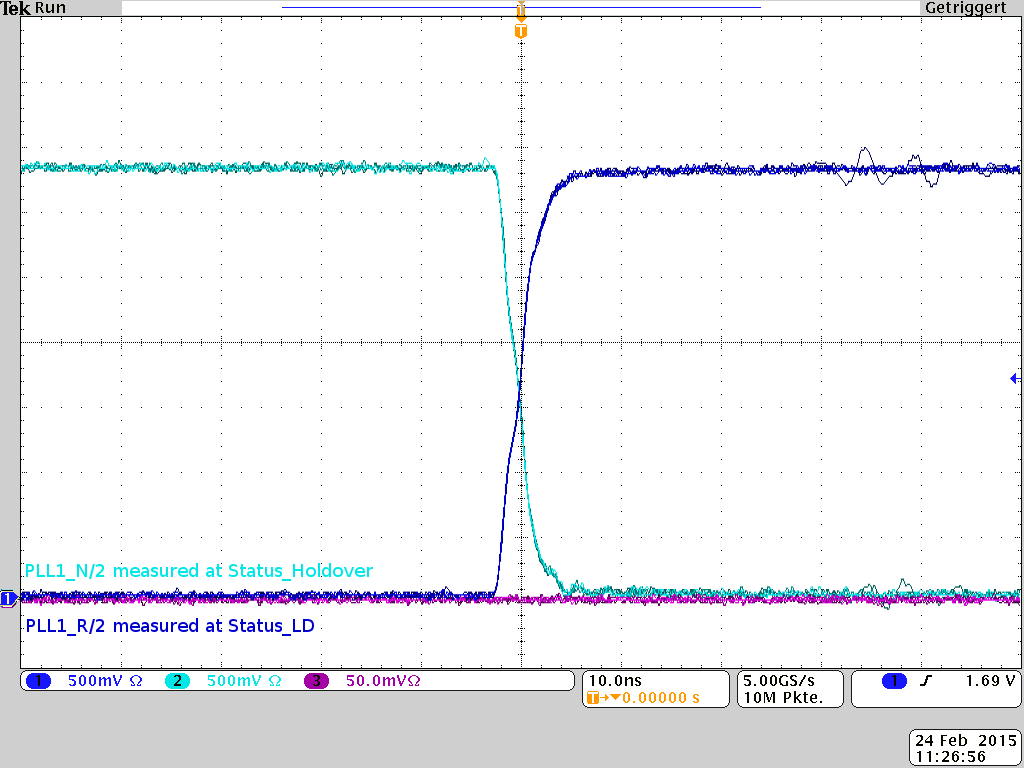
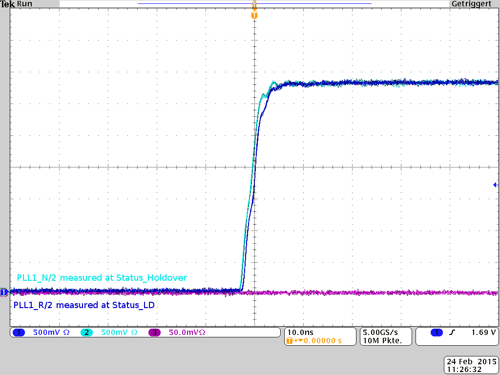
    To measure the static phase offset between PLL1 reference & feedback signals simultaneously, you can output the PLL1 R/2 signal on Status_LD pin (LD_MUX bits = "PLL1 R/2") and output the PLL N/2 signal on Status_Holdover pin (HOLDOVER_MUX bits = "PLL1 N/2"), probe on both status signals using scope probes, and measure the phase offset between the rising edges of the 25 MHz signal (= PLL1 R/2 = PLL2 N/2). Your programmed PLL1 lock detect window should be greater than the phase offset in order for the lock detection circuit to indicate lock).

    Also, to reduce the static phase offset, I suggest using a higher PLL1 PFD frequency = 100 kHz (PLL1_R = PLL1_N = 500) or 1 MHz (PLL1_R = PLL2_N = 50). You may need to re-optimize your PLL1 charge pump current and loop filter values for the desired loop bandwidth and stability.

    Regards,
    Alan
  • Dear Alan,

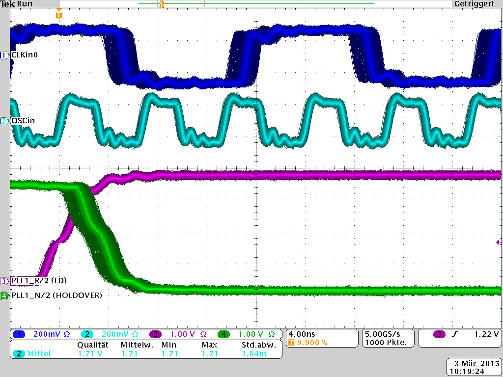
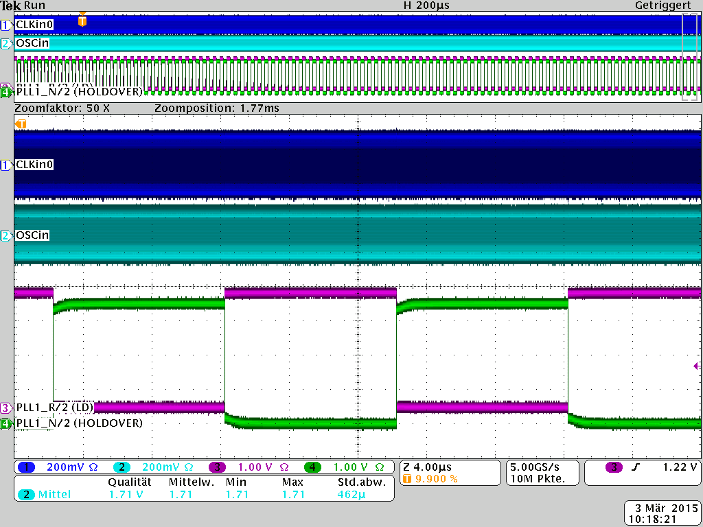
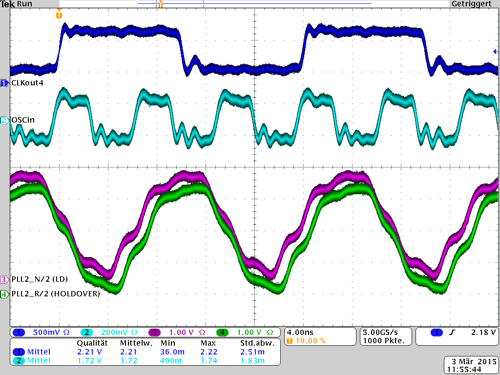
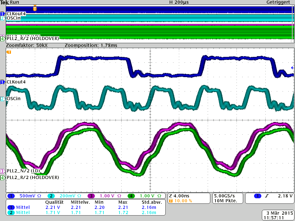
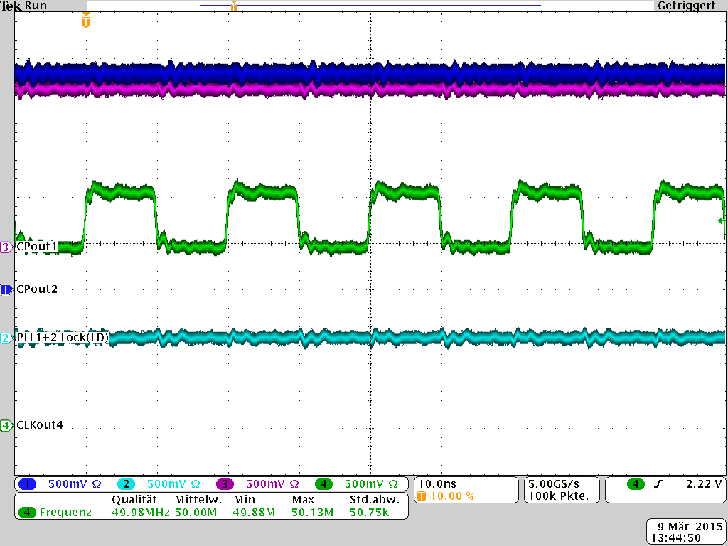
    We changed our LMK04816 programming so we can measure "PLL1 N/2" and "PLL1 R/2" on the Status_LD and Status_Holdover pins. What we see is that PLL1 N/2 and PLL1 R/2 are "edge aligned". Sometimes the rising edges of N and R are aligned, and sometimes the rising edge of N is aligned to the falling edge of R. You can see it in the following two pictures:

    I think this is because we are looking at N/2 and R/2, is this right?

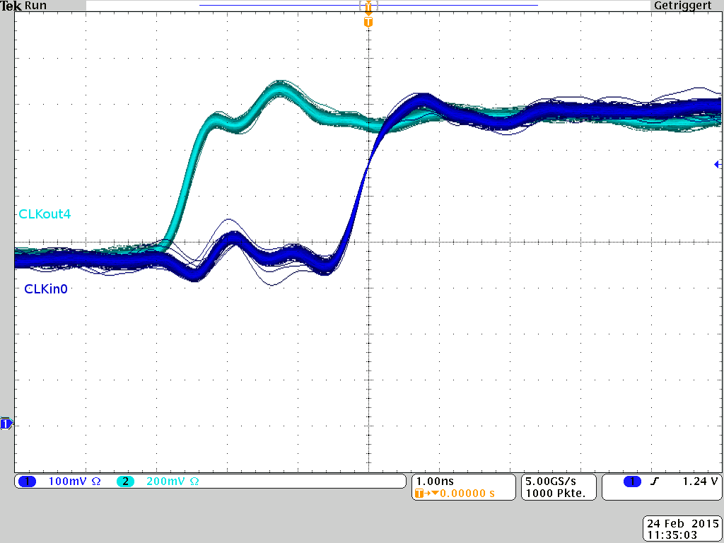
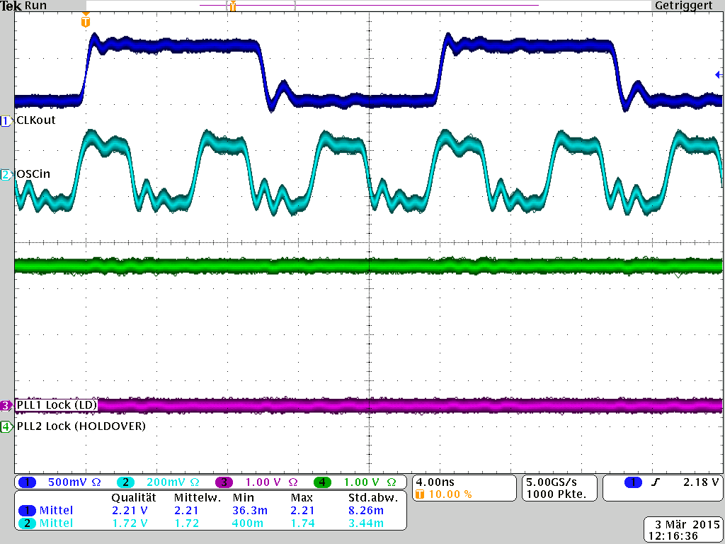
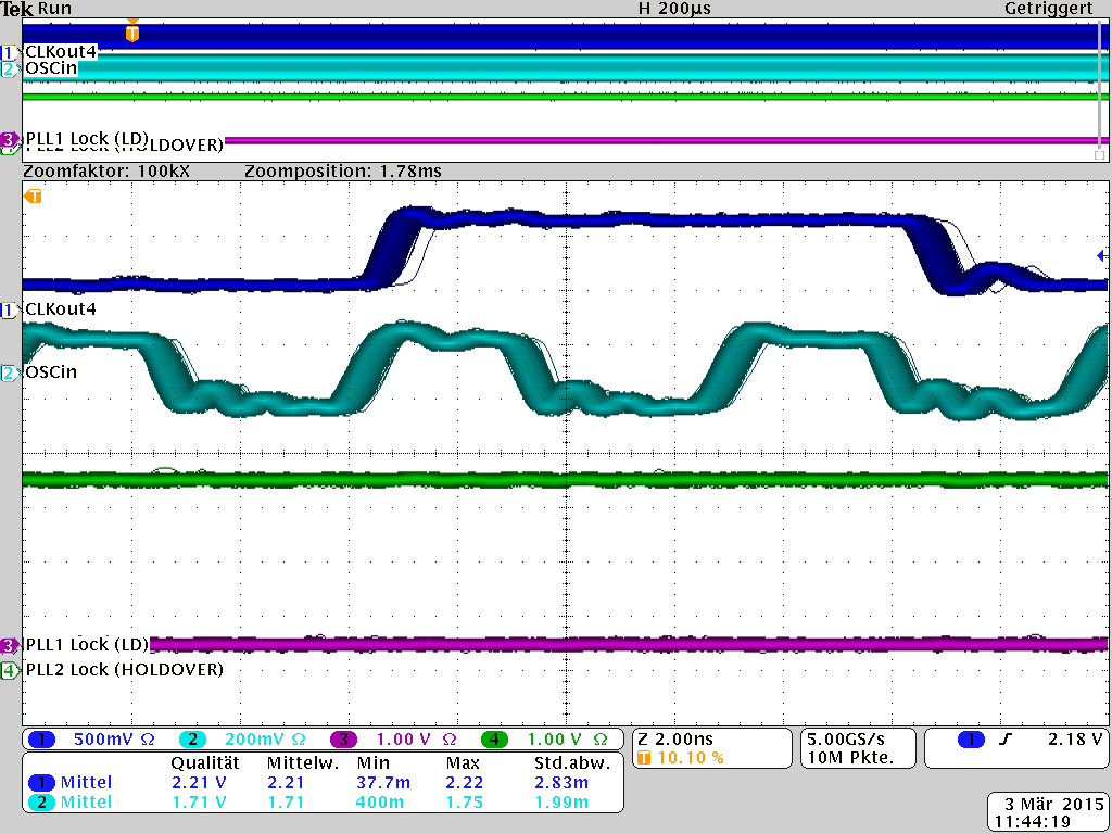
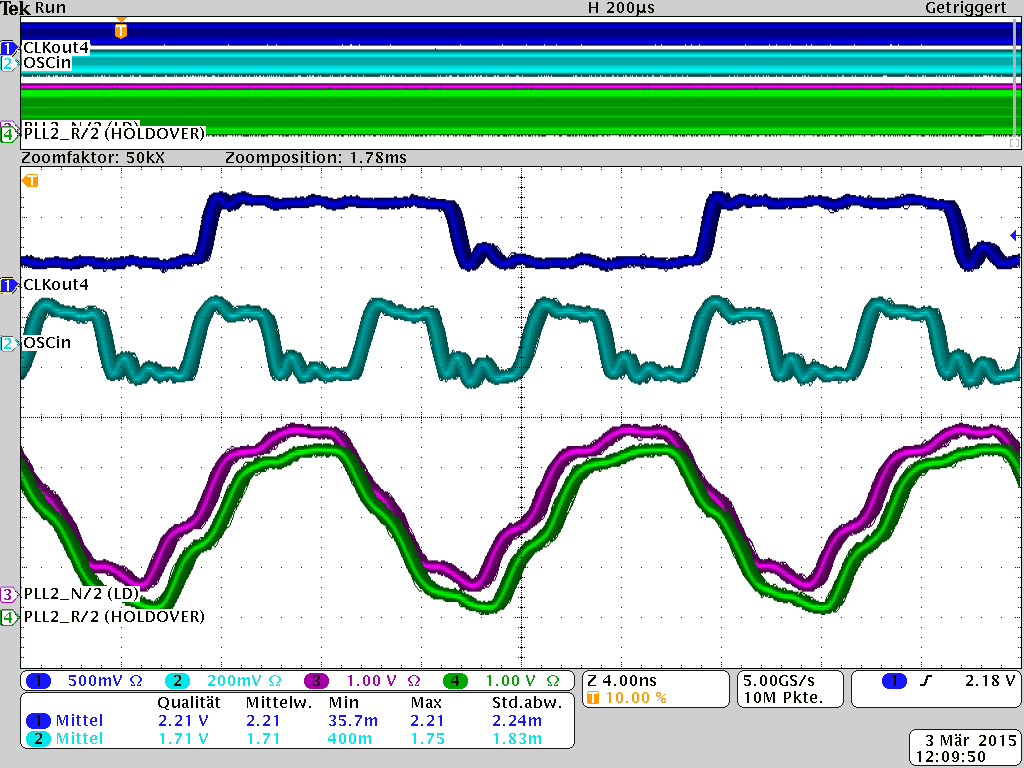
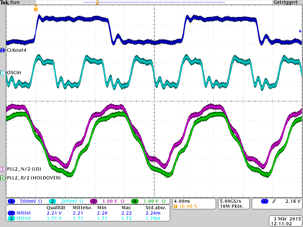
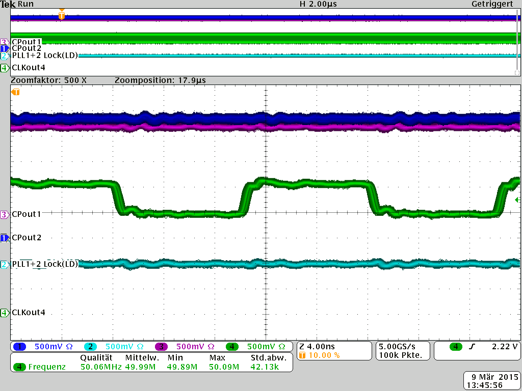
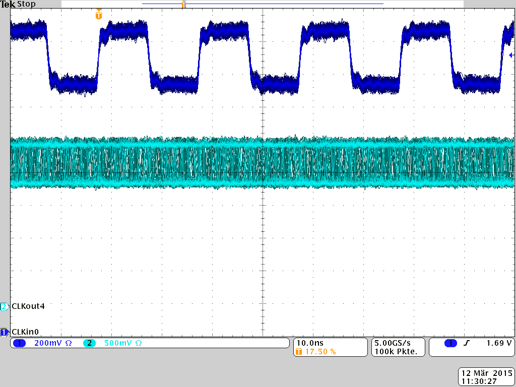
    Now we reprogrammed the LMK04816 with our original settings, and probed CLKin0 and CLKout4. Since the LMK is in 0-delay mode, they should be phase aligned, too. As you can see on the next picture, they are phase aligned:

    My assumption is that the 3.5ns delay between the two clocks comes from the fact that we use internal 0-delay mode. With internal 0-delay mode, the delay of input and output buffers is not included in the loop what leads to the static phase difference we see in the picture. Do you agree?

    But the Status_LD pin, which is programmed to show us the lock of PLL1 and PLL2 stays low. And low means "no lock".
    Any further ideas?

    Regards,
    Niels

  • without an answer from TI, we did some additional tests.

    First, we removed 0-delay from our LMK04816 configuration and changed LD_Status to output PLL1_DLD only.
    In this configuration, we see PLL1 lock. But a bit of cold air is enough to let PLL1 lose its lock.

    How can we make PLL1 more stable?

    Second, we changed the function of LD_Status to output PLL2_DLD in the above configuration. But we never see a lock of PLL2.
    The external Loop-Filter of PLL2 (calculated by Clock Design Tool) is C1=47pF || C2=4.7nF + R2=470R.
    Is this ok, or do you suggest something else?

    What can prevent PLL2 from locking when PLL1 is locked and 0-delay mode is NOT used?

    Third, we set PLL2_WND_SIZE to 0x3 (reserved), and by miracle we get a lock of PLL2.
    Please explain this to me.

    I am looking forward to your answer.

    Regards,
    Niels

  • I didn't get a chance to look into this question today, but I notified a colleague based in Germany to see if he could respond before I can.

    Regards,
    Alan

  • Dear Alan,

    I just found out that our manufacturing populated LMK04806 devices instead of the LMK04816 I wanted to use. Perhaps this is the reason for all the trouble?
    Please be so kind and tell me the differences between
    LMK04816
    and
    LMK04806

    I got to go now and visit our manufacturing. I'm in the mood for some bloody action, and I know whom to invite ... ;-)
    I think I'll be back in an hour, awaiting your answer.

    King Regards,
    Niels
  • Dear Alan,
    I'm back again,a and I calmed down a bit.
    I already had a look into the LMK04806 data sheet. The only difference I found, is CLKin2.
    By luck, weare not using CLKin2.
    I also used CoadLoader to generate a register-set for the LMK04806, and it's identical to the one we use now.

    As I already said before: Any input from your side is welcome to solve this issue.

    Regards,
    Niels
  • Please send your application schematic and latest Codeloader Mac file.  Also, we need your VCXO datasheet with the key specs like APR, Vc input range (to calculate Kv), and Vc input resistance. We need to check loop filter values and loop response.  

    Alan

  • Good morning Alan,

    here are the requested documents.

    Schematic:
    TAMC532_Clock-Distribution_001.pdf

    CodeLoader File:

    LMK04806_RegInit_Set0-mac.txt
    [SETUP]
    ADDRESS=888
    CLOCK=4
    DATA=2
    LE=6
    PART=LMK04806B
    PINPOSITION00=1
    PINPOSITION01=7
    PINPOSITION02=5
    PINPOSITION03=10
    [MODES]
    NAME00=R0 (INIT)
    VALUE00=2148925760
    NAME01=R0
    VALUE01=1312256
    NAME02=R1
    VALUE02=1312257
    NAME03=R2
    VALUE03=1312258
    NAME04=R3
    VALUE04=1312259
    NAME05=R4
    VALUE05=1312260
    NAME06=R5
    VALUE06=1312261
    NAME07=R6
    VALUE07=51773446
    NAME08=R7
    VALUE08=50528263
    NAME09=R8
    VALUE09=50528264
    NAME10=R9
    VALUE10=1431655753
    NAME11=R10
    VALUE11=2432846090
    NAME12=R11
    VALUE12=335556619
    NAME13=R12
    VALUE13=453771628
    NAME14=R13
    VALUE14=991105133
    NAME15=R14
    VALUE15=318767118
    NAME16=R15
    VALUE16=41975823
    NAME17=R16
    VALUE17=22348816
    NAME18=R24
    VALUE18=24
    NAME19=R25
    VALUE19=16842777
    NAME20=R26
    VALUE20=2947022874
    NAME21=R27
    VALUE21=470082075
    NAME22=R28
    VALUE22=2417180
    NAME23=R29
    VALUE23=41943325
    NAME24=R30
    VALUE24=33554718
    NAME25=R31
    VALUE25=2031647
    OSCIN00=50
    EXTRA_PLL_N_DIV_1_00=1
    OSCIN01=150
    EXTRA_PLL_N_DIV_1_01=1
    PINS=513
    [BURST]
    COUNT=0
    [FLEXHASH]
    HASHVALUE=0
    

    VCXO Data Sheet:
    IDT_8N3QV01_DST_20120307.pdf
    The VCXO is programmed to 150MHz and 100ppm/V pull-range.

    I am looking forward to your answer.

    Regards,
    Niels

  • Hello Niels,

    let me get up to speed and look into your challenge.

    Some questions + answers from my side:

    4816 & 4806:

    Please check the detailed block diagrams in the data sheets. Main differences are the CLKin2 & OSCout1! So basically you get an additional input on the 4816 vs an additional VCXO copy output on the 4806. I need to check the details of the bitmap to see what happens when you program the setting of the other device.

    One observation from your MAC file which might explain the issue ...

    I think your PLL2_N divider might be set not deep enough.

    Please let me know if this was the issue. If not, please let me know which VCXO you have and where your CLKin input source comes from.

    Thanks!


    Best regards,

    Patrick

  • Hello Patrick,
    PLL2_N_Pre = 2 and PLL2_N = 8
    With 2.4GHz VCO, this results in 150MHz PDF of PLL2.
    The external VCXO of PLL1 is running at 150MHz. I think that fits.

    And as I already wrote: We see the correct frequency on CLKoutX_Y, but we do not achieve PLL1 & 2 lock status.
    Without 0-delay mode, we get a PLL1 lock, but a bit of cold airflow is suficient to remove the lock status.

    Any further suggestions?

    Regards,
    Niels
  • Hello Niels,
    sorry I was writing my reply while you replied, so I missed the schematics.
    The VCXO control voltage input has 500kOhm, that should be high ohmic enough.
    Did you check the control voltages with a high impedance probe for noise?

    >>First, we removed 0-delay from our LMK04816 configuration and changed LD_Status to output PLL1_DLD only.
    >>In this configuration, we see PLL1 lock. But a bit of cold air is enough to let PLL1 lose its lock.
    >>
    >>How can we make PLL1 more stable?
    >>
    >>Second, we changed the function of LD_Status to output PLL2_DLD in the above configuration. But we never see a lock of PLL2.
    >>The external Loop-Filter of PLL2 (calculated by Clock Design Tool) is C1=47pF || C2=4.7nF + R2=470R.
    >>Is this ok, or do you suggest something else?
    >>
    >>What can prevent PLL2 from locking when PLL1 is locked and 0-delay mode is NOT used?

    The loop filters should be ok.

    With the temperature sensitivity it seems that basically all loops are very sensitive.

    Is there a chance you can measure all PFD signal on the status pins at once?

    Did you use codeloader only to generate the settings or do you have an EVM as well?


    Best regards,
    Patrick
  • Sorry, we have no evaluation  board.

    We use CoadLoader only to generate the register map.

    I have a 4  channel 1GHz scope and active probes. If you tell me what you want to see, I will do the measjrements.

    Regards,

    Niels

  • Hello all,

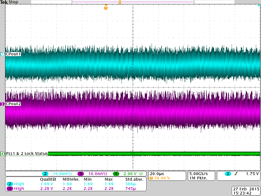
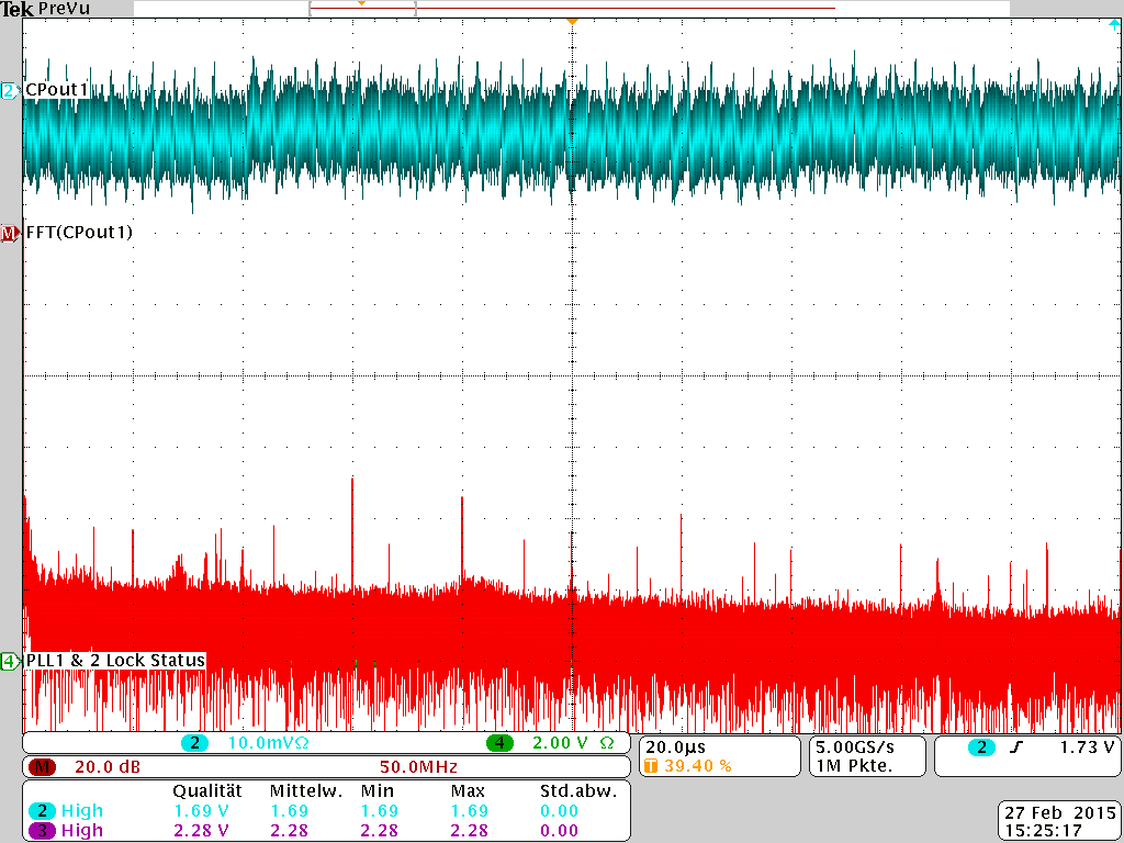
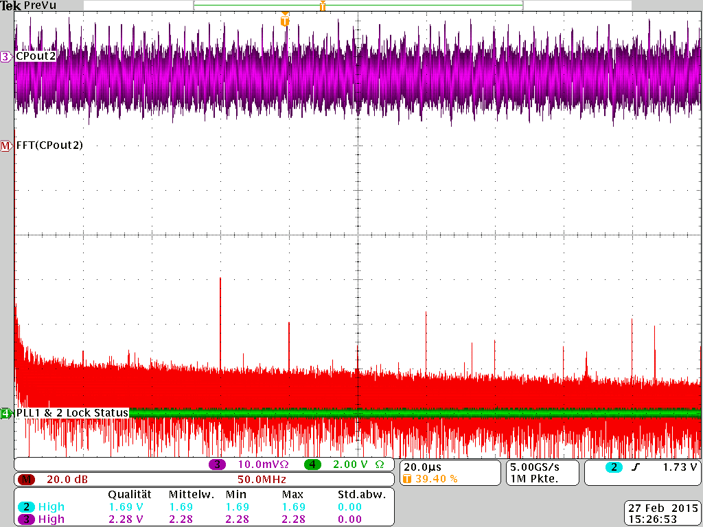
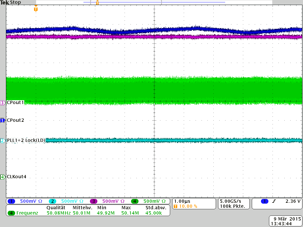
    I did some measurements of the CPout1 and CPout2 signals. For DC-level, see the scope's measurement at the bottom of the pictures.
    The first one gives you a coarse overview:

    Now I configured the scope to calculated the FFT of both CPout signals.

    CPout1:

    CPout2:


    Can you see anything that helps?

    Regards,
    Niels

  • Hello Niels,
    thanks for making the scope shots!
    In the first FFT scope shot from CPout1, PLL1 is unlocked, correct? (green line in the background?)

    I will post some configurations and a guideline in some minutes, so that you can check the device step by step.
    Your scope will come in handy to measure the signals from the PFDs again.
    I want to search for a capture of the point in time where the a PLL unlocks. Therefore you will need to do a skew/ setup/hold measurement and create a track waveform.

    Best regards,
    Patrick

  • Hello Patrick,
    yes, the combined PLL1 & 2 Lock Status is 0 (unlocked) in all three pictures.

    Regards,
    Niels
  • Hello Niels,

    thanks for the confirmation of the lock status in the captures!

    I created test configurations for you (renamed codeloader .mac files).

    1. Dual Loop Setup to test the first PLL.
      1. Load the registers from the "LMK04806_DualLoopintVCO_PLL1_PFD_100k" using the recommended sequence
      2. pull RESET in R0; then reprogram R0 with actual values, then continue in order R0..R31.
      3. PLL1 lock detect is on STATUS_LD, PLL2 lock detect is on HOLDOVER_MUX
    2. Please observe the following signals:
      1. CLKin0
      2. OSCin
      3. PLL1 lock on STATUS_LD
      4. PLL2 lock on HOLDOVER_MUX
    3. Please check if the device indicates lock or not.
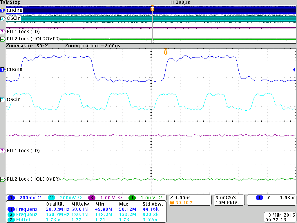
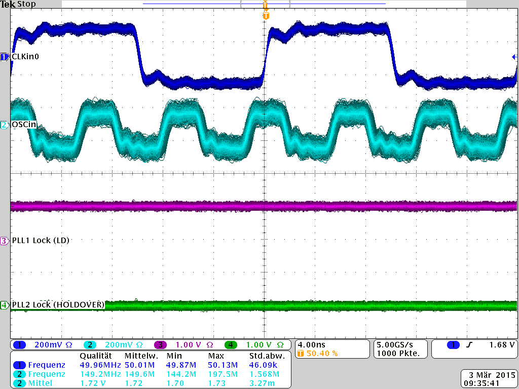
      1. Use a longer capture time and use a "track waveform" to see how the phase of the input and output moves (and have the indicated lock status in the capture).
      2. Please observe, like you did before, in persistence mode, so we can see any jumps of the input or output.
    4. Change Status signals
      1. PLL1_R/2 is on STATUS_LD, PLL1_N/2 is on HOLDOVER_MUX
      2. For crosscheck I created a mac "LMK04806_DualLoopintVCO_PLL1_PFD_100k_check" as reference.
    5. Please observe the following signals:
      1. CLKin0
      2. OSCin
      3. PLL1_R/2 on STATUS_LD
      4. PLL1_N/2 on HOLDOVER_MUX
      5. Try to capture a similar shot like before. The goal is to understand if the PLL actually unlocks or if the indicator setting does not match to the settings.
    6. Please also let me know if there are any vibrations in your application which could influence the (packaged) VCXO.
    7. Single Loop Setup to test the second PLL.
      1. Load the registers from the "LMK04806_SingleLoopintVCO_PLL2_PFD_150M" using the recommended sequence
      2. pull RESET in R0; then reprogram R0 with actual values, then continue in order R0..R31.
      3.  PLL2 lock detect is on HOLDOVER_MUX (still: PLL1 lock detect is on STATUS_LD)
    8. Please observe the following signals:
      1. OSCin
      2. CLKout0 or CLKout4
      3. PLL2 lock on HOLDOVER_MUX
      4. Try to capture a similar shot like before. The goal is to understand if the PLL actually unlocks or if the indicator setting does not match to the settings.
    9. Force Holdover Mode
      1. Activate the holdover mode (see FORCE_HOLDOVER bit)
      2. you can use the mac "LMK04806_SingleLoopintVCO_PLL2_PFD_150M_check_holdover" as reference
    10. Change Status signals
      1. PLL2_R/2 is on STATUS_LD, PLL2_N/2 is on HOLDOVER_MUX

    11. Please observe the following signals:
      1. OSCin
      2. CLKout0 or CLKout4
      3. PLL1_R/2 on STATUS_LD
      4. PLL1_N/2 on HOLDOVER_MUX
      5. Try to capture a similar shot like before.

    Best regards,

    Patrick

    Attachments:

    LMK04806_DualLoopintVCO_PLL1_PFD_100k.txt
    [SETUP]
    ADDRESS=888
    CLOCK=4
    DATA=2
    LE=6
    PART=LMK04806B
    PINPOSITION00=1
    PINPOSITION01=7
    PINPOSITION02=5
    PINPOSITION03=10
    [MODES]
    NAME00=R0 (INIT)
    VALUE00=2148925760
    NAME01=R0
    VALUE01=1312256
    NAME02=R1
    VALUE02=2148794689
    NAME03=R2
    VALUE03=1312258
    NAME04=R3
    VALUE04=2148794435
    NAME05=R4
    VALUE05=2148794692
    NAME06=R5
    VALUE06=2148794693
    NAME07=R6
    VALUE07=786438
    NAME08=R7
    VALUE08=196615
    NAME09=R8
    VALUE09=8
    NAME10=R9
    VALUE10=1431655753
    NAME11=R10
    VALUE11=2416066826
    NAME12=R11
    VALUE12=67178507
    NAME13=R12
    VALUE13=185335916
    NAME14=R13
    VALUE14=318930989
    NAME15=R14
    VALUE15=33554446
    NAME16=R15
    VALUE16=2147516431
    NAME17=R16
    VALUE17=3243574288
    NAME18=R24
    VALUE18=88
    NAME19=R25
    VALUE19=46777369
    NAME20=R26
    VALUE20=2947022874
    NAME21=R27
    VALUE21=268467483
    NAME22=R28
    VALUE22=2193180
    NAME23=R29
    VALUE23=25166109
    NAME24=R30
    VALUE24=33554718
    NAME25=R31
    VALUE25=2031647
    OSCIN00=50
    EXTRA_PLL_N_DIV_1_00=1
    OSCIN01=150
    EXTRA_PLL_N_DIV_1_01=1
    PINS=513
    [BURST]
    COUNT=0
    [FLEXHASH]
    HASHVALUE=0
    

    LMK04806_SingleLoopintVCO_PLL2_PFD_150M.txt
    [SETUP]
    ADDRESS=888
    CLOCK=4
    DATA=2
    LE=6
    PART=LMK04806B
    PINPOSITION00=1
    PINPOSITION01=7
    PINPOSITION02=5
    PINPOSITION03=10
    [MODES]
    NAME00=R0 (INIT)
    VALUE00=2148925760
    NAME01=R0
    VALUE01=1312256
    NAME02=R1
    VALUE02=2148794689
    NAME03=R2
    VALUE03=1312258
    NAME04=R3
    VALUE04=2148794435
    NAME05=R4
    VALUE05=2148794692
    NAME06=R5
    VALUE06=2148794693
    NAME07=R6
    VALUE07=786438
    NAME08=R7
    VALUE08=196615
    NAME09=R8
    VALUE09=8
    NAME10=R9
    VALUE10=1431655753
    NAME11=R10
    VALUE11=2416066826
    NAME12=R11
    VALUE12=872484875
    NAME13=R12
    VALUE13=185335916
    NAME14=R13
    VALUE14=318930989
    NAME15=R14
    VALUE15=33554446
    NAME16=R15
    VALUE16=2147516431
    NAME17=R16
    VALUE17=3243574288
    NAME18=R24
    VALUE18=88
    NAME19=R25
    VALUE19=46777369
    NAME20=R26
    VALUE20=2947022874
    NAME21=R27
    VALUE21=268467483
    NAME22=R28
    VALUE22=2193180
    NAME23=R29
    VALUE23=25166109
    NAME24=R30
    VALUE24=33554718
    NAME25=R31
    VALUE25=2031647
    OSCIN00=50
    EXTRA_PLL_N_DIV_1_00=1
    OSCIN01=150
    EXTRA_PLL_N_DIV_1_01=1
    PINS=513
    [BURST]
    COUNT=0
    [FLEXHASH]
    HASHVALUE=0
    

    LMK04806_DualLoopintVCO_PLL1_PFD_100k_check.txt
    [SETUP]
    ADDRESS=888
    CLOCK=4
    DATA=2
    LE=6
    PART=LMK04806B
    PINPOSITION00=1
    PINPOSITION01=7
    PINPOSITION02=5
    PINPOSITION03=10
    [MODES]
    NAME00=R0 (INIT)
    VALUE00=2148925760
    NAME01=R0
    VALUE01=1312256
    NAME02=R1
    VALUE02=2148794689
    NAME03=R2
    VALUE03=1312258
    NAME04=R3
    VALUE04=2148794435
    NAME05=R4
    VALUE05=2148794692
    NAME06=R5
    VALUE06=2148794693
    NAME07=R6
    VALUE07=786438
    NAME08=R7
    VALUE08=196615
    NAME09=R8
    VALUE09=8
    NAME10=R9
    VALUE10=1431655753
    NAME11=R10
    VALUE11=2416066826
    NAME12=R11
    VALUE12=67178507
    NAME13=R12
    VALUE13=1661730924
    NAME14=R13
    VALUE14=2197979181
    NAME15=R14
    VALUE15=33554446
    NAME16=R15
    VALUE16=2147516431
    NAME17=R16
    VALUE17=3243574288
    NAME18=R24
    VALUE18=88
    NAME19=R25
    VALUE19=46777369
    NAME20=R26
    VALUE20=2947022874
    NAME21=R27
    VALUE21=268467483
    NAME22=R28
    VALUE22=2193180
    NAME23=R29
    VALUE23=25166109
    NAME24=R30
    VALUE24=33554718
    NAME25=R31
    VALUE25=2031647
    OSCIN00=50
    EXTRA_PLL_N_DIV_1_00=1
    OSCIN01=150
    EXTRA_PLL_N_DIV_1_01=1
    PINS=513
    [BURST]
    COUNT=0
    [FLEXHASH]
    HASHVALUE=0
    

    LMK04806_SingleLoopintVCO_PLL2_PFD_150M_check.txt
    [SETUP]
    ADDRESS=888
    CLOCK=4
    DATA=2
    LE=6
    PART=LMK04806B
    PINPOSITION00=1
    PINPOSITION01=7
    PINPOSITION02=5
    PINPOSITION03=10
    [MODES]
    NAME00=R0 (INIT)
    VALUE00=2148925760
    NAME01=R0
    VALUE01=1312256
    NAME02=R1
    VALUE02=2148794689
    NAME03=R2
    VALUE03=1312258
    NAME04=R3
    VALUE04=2148794435
    NAME05=R4
    VALUE05=2148794692
    NAME06=R5
    VALUE06=2148794693
    NAME07=R6
    VALUE07=786438
    NAME08=R7
    VALUE08=196615
    NAME09=R8
    VALUE09=8
    NAME10=R9
    VALUE10=1431655753
    NAME11=R10
    VALUE11=2416066826
    NAME12=R11
    VALUE12=872484875
    NAME13=R12
    VALUE13=1930166380
    NAME14=R13
    VALUE14=2466414637
    NAME15=R14
    VALUE15=33554446
    NAME16=R15
    VALUE16=2147516431
    NAME17=R16
    VALUE17=3243574288
    NAME18=R24
    VALUE18=88
    NAME19=R25
    VALUE19=46777369
    NAME20=R26
    VALUE20=2947022874
    NAME21=R27
    VALUE21=268467483
    NAME22=R28
    VALUE22=2193180
    NAME23=R29
    VALUE23=25166109
    NAME24=R30
    VALUE24=33554718
    NAME25=R31
    VALUE25=2031647
    OSCIN00=50
    EXTRA_PLL_N_DIV_1_00=1
    OSCIN01=150
    EXTRA_PLL_N_DIV_1_01=1
    PINS=513
    [BURST]
    COUNT=0
    [FLEXHASH]
    HASHVALUE=0
    

    LMK04806_SingleLoopintVCO_PLL2_PFD_150M_check_holdover.txt
    [SETUP]
    ADDRESS=888
    CLOCK=4
    DATA=2
    LE=6
    PART=LMK04806B
    PINPOSITION00=1
    PINPOSITION01=7
    PINPOSITION02=5
    PINPOSITION03=10
    [MODES]
    NAME00=R0 (INIT)
    VALUE00=2148925760
    NAME01=R0
    VALUE01=1312256
    NAME02=R1
    VALUE02=2148794689
    NAME03=R2
    VALUE03=1312258
    NAME04=R3
    VALUE04=2148794435
    NAME05=R4
    VALUE05=2148794692
    NAME06=R5
    VALUE06=2148794693
    NAME07=R6
    VALUE07=786438
    NAME08=R7
    VALUE08=196615
    NAME09=R8
    VALUE09=8
    NAME10=R9
    VALUE10=1431655753
    NAME11=R10
    VALUE11=2416066826
    NAME12=R11
    VALUE12=872484875
    NAME13=R12
    VALUE13=1930166380
    NAME14=R13
    VALUE14=2466414637
    NAME15=R14
    VALUE15=33554446
    NAME16=R15
    VALUE16=2147516463
    NAME17=R16
    VALUE17=3243574288
    NAME18=R24
    VALUE18=88
    NAME19=R25
    VALUE19=46777369
    NAME20=R26
    VALUE20=2947022874
    NAME21=R27
    VALUE21=268467483
    NAME22=R28
    VALUE22=2193180
    NAME23=R29
    VALUE23=25166109
    NAME24=R30
    VALUE24=33554718
    NAME25=R31
    VALUE25=2031647
    OSCIN00=50
    EXTRA_PLL_N_DIV_1_00=1
    OSCIN01=150
    EXTRA_PLL_N_DIV_1_01=1
    PINS=513
    [BURST]
    COUNT=0
    [FLEXHASH]
    HASHVALUE=0
    

  • Patrick,

    unfortunately, I was our of office during the day, and now my software-guy who does the LMK-programming is already at home.

    I will come back tomorrow.

    King regards,
    Niels

  • Patrick and Alan,

    the board resides on my table in the lab, no shock or vibration at all.

    I programmed the LMK04806 with your "LMK04806_DualLoopintVCO_PLL1_PFD_100k" register-set, and got the following pictures (PLL1 is locked, CH3 had a DC-offset programmed in the scope) :

    Now I removed the lousy DC-offset of CH3 and programmed the "LMK04806_DualLoopintVCO_PLL1_PFD_100k_check" settings:

    With the "LMK04806_SingleLoopintVCO_PLL2_PFD_150M" settings programmed into the LMK04806:

    "LMK04806_SingleLoopintVCO_PLL2_PFD_150M_check" settings:

    And now, the pics from the "LMK04806_SingleLoopintVCO_PLL2_PFD_150M_check_holdover" setting:

    I hope this is helpful. If you need any other measurements, please tell me.

    Regards,
    Niels

  • Hello Niels,
    thanks for sharing all the measurement data! This is very helpful. It is good to see we can get the individual loops working. Let me do some more thinking and I'll try to get you back on your original configuration (or similar).

    Best regards,
    Patrick
  • LMK04806_RegInit_Set0_Proposal.macHello Niels,

    I rebuilt your original configuration for the LMK4806. The changes are higher PFD1 frequency, little increased PFD1 window (please try if you can decrease again and check if the loop stays in lock and what it indicates), more DLD_CNT cycles. Unfortunately I lack a VCXO for 150MHz, so I can't crosscheck myself.

    Please let me know if this works as well.

    Best regards,

    Patrick

  • Hello Patrick,

    I tried your new setting, and here are the results:

    As you can see, Status_LD is low, meaning one or both PLLs do not match?
    Here come some more shots of the same signals

    I also observed, that the CPout2 "frequency" varies, when I slightly move the probe at CPout2 without interrupting the contact between probe and signal. You can see it in the following video (sorry for the crazy orientation, I missed to pay my gravity-bill):

    I am looking forward to your answer.

    King Regards,
    Niels

  • Hello Niels,
    sorry for the delay in reply.
    The first screenshot with the triangular signal on the CPOUT2 hopefully comes from noise injected through the probes. I assume the CLKin to CLKout4 is not locked?

    Best regards,
    Patrick
  • Patrick,
    I'm sorry, but I don't think that the triangular waveform is noise. It's the same signal as the yellow one in the Video.
    Form my point oft view, it's PLL2 that tries to achieve a lock.
    How do you explain that moving the Probe without interrupting the contact between Probe and signal changes the triangular frequency?
    I will do more measurements tomorrow to check lock between clkin and clkout.

    Regards,
    Niels
  • Hi Niels,

    Since Patrick had stepped in to help you debug, I lost track of the issue somewhat. Here are some comments based on the situation as I understand it (my apologies if I missed something).

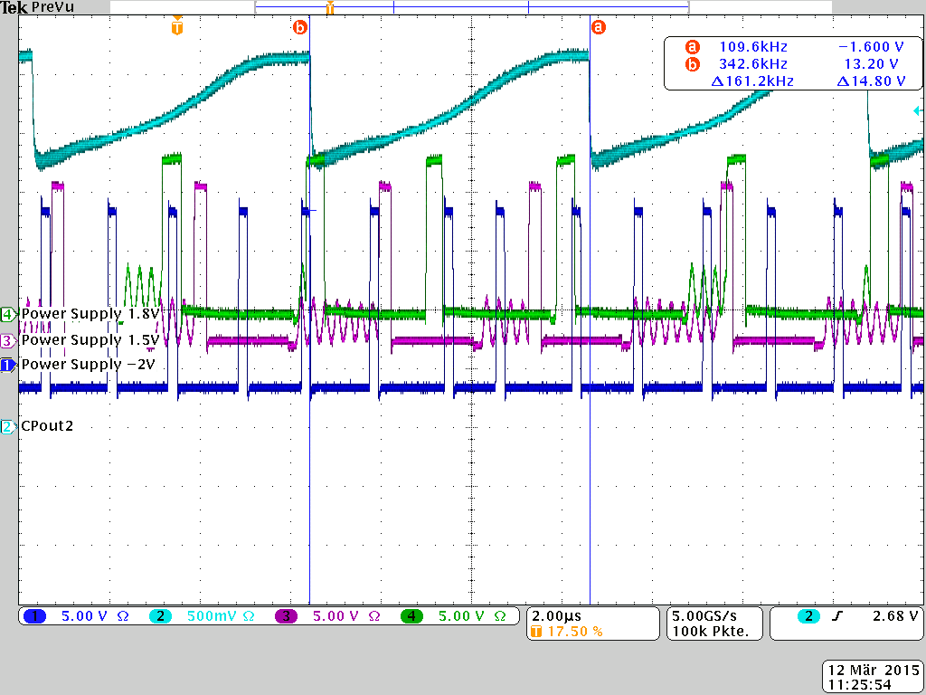
    When you measured the triangular-shaped waveform on CPOUT2, was the probe's ground lead connected? From the video, the ground lead appears to be disconnected. Perhaps that's why you see that triangular waveform instead of a steady voltage. I assume the probe is high impedance (Mohm?) to avoid charge leakage. The period of the triangular waveform appears close to 250 kHz; is there a switching regulator nearby?

    Can you confirm if the output frequency is locked to the input frequency when you observe the these signals on the scope? If so, then it may not be an actual PLL lock problem but rather a Lock detection/indication issue. Lock detection issues can be related to static phase offset at the PLL's PFD inputs due to charge leakage on the VCXO/VCO Vctrl inputs (check for leaky loop filter caps, flux residue from loop filter rework, or probe loading) , or dynamic phase offsets or tracking skew (check for excessive high input clock jitter or other sources of VCXO phase drift/modulation like temperature, microphonics on MLCC loop filter caps or VCXO). If the combined static + dynamic phase offsets exceed the DLD lock detector window, then it's possible that the DLD will not indicate lock even though the PLL is actually locked and stable.

    Can you determine if PLL1 or PLL2's DLD signal is causing the combined "PLL1 & PLL2 DLD" signal to be low? Try looking at Status_LD output with LD_MUX = "PLL1 DLD" (R12[31:27] = d'1) and then "PLL2 DLD" (R12[31:27] = d'2) to determine which PLL or if both PLL's lock status is causing the Status_LD output to be low.

    Usually I see more cases where PLL1 DLD signal is causing the lock status issue.

    If PLL1 DLD status is Low, I suggest you try the following and check if PLL1 DLD indicates lock?
    1. Increase PLL1_WND_SIZE to "40 ns" DLD window (R24[7:6]) = b'11).
    2. Increase PLL1_CP_GAIN to "400 uA" (R27[27:26] = b'10) to increase PLL bandwidth.
    3. Check loop filter for leaky caps, flux residue, or probe loading that could introduce excessive charge leakage and static phase offset.
    4. Check if input clock cycle-cycle jitter is larger than the programmed lock window, or other potential causes for dynamic phase offset as mentioned above.

    By the way, are you powering the LMK device with a LDO regulator or DC/DC?

    Regards,
    Alan
  • Hi Alan and Patrick,

    welcome back to this nasty little problem, Alan. I will now try to answer all your questions:
    - The probe-ground is connected to the (grounded) metal plate above the LMK04806 by a solid wire. In the video, it's hidden by the probe itself.
    - The probe is an active voltage probe with 1M Ohm and <1pF
    - You are right, there are three switching regulators nearby. I made a scope shot of CPout2 and the switching nodes of all three switchers. IMHO, there is no relationship between them. What do you think about it?

    - As you can see in the next scope shot, the output frequency (CLKout4) is not locked to the input frequency (CLKin0):

    We tried PLL1_DLD and PLL2_DLD on Status_LD, and both are "low" (no lock).

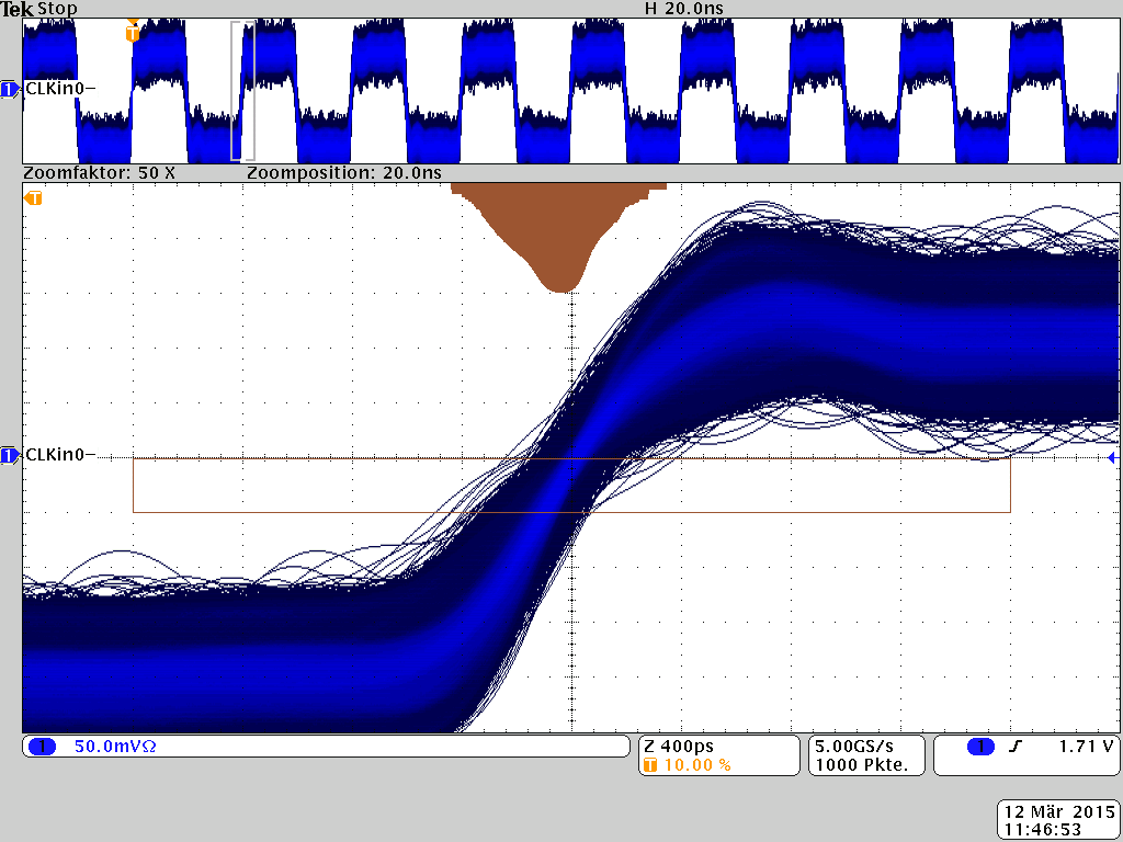
    - Please see the following picture for cycle-cycle jitter of CLKin0 (the brown thing is a histogram with log. y-axis scale):

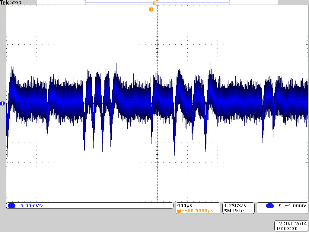
    - Yes, the LMK is powered by a switching regulator. The following picture shows the measured power-supply noise prior to the LMK power-supply-filters (+-10mVpp):

    I use the good old handheld multimeter and measured the resistance between both CPout and ground:
    CPout1: 2.3M Ohm
    CPout2: 2.5M Ohm
    Is this ok, or does this lead to excessive charge pump leakage?

    This was all done with Patricks last register-set.

    Regards,
    Niels

  • Hello Niels,
    before we go further into the whole noise topic:
    The root cause must be in the differences between the two trial settings I sent earlier and the last settings where I tried to replicate your frequency plan.

    Can you please try to switch off the CLKout6?
    Powerdown the stage in R7 and also try the output channel in R3.
    The other configs only had CLKout0 and CLKout4 active.
    The last config has CLKout6 active, which is powered by the VCC11 where rework is required according to the schematic.
    I just want to rule out that this impacts the nested feedback loop coming from a CLKout before we deep dive into noise sources (as the "normal" feedback paths seem to be clean).

    Best regards,
    Patrick

  • Hello Patrick,

    I powered dwon CLKout6 as you suggested, but it did not change anything.

    I have a question to you and Alan:
    What will happen if I remove all external CPout filter-components? Perhaps this is a way to check if there is a leakage problem.

    Best Regards,
    Niels

    P.S.: I sometimes get a mail when you or alan write a post, but in most cases I don't get any mail. That's the reason why I am often a delayed  in my relpy. The "Notify me when someone replies to this post" box is always checked.

  • Niels,

    In your latest scope plots, the triangular waveform looks different and has asymmetrical ramp rates (before it was more symmetric). What is different in the setup?

    If you remove the external loop filter components, the PLLs will not be able to lock if you're trying to operate the device.

    Does this issue occur on multiple devices/boards?  Have you tried replacing/swapping the device to see if the issue follows the device vs. board?
     
    Regards,
    Alan

  • Alan,

    you are right, the waveform of CPout2 differs, but I don't konw what was different when I measured the triangle, except that I now removed the grounded copper-plate on top of the LMK04816.

    I just cross-checked it with a second board (no grounded copper-plate on top of LMK04806, too), and it shows the same CPout2 waveform (no triangle)

    Regards,
    Niels

  • Niels,

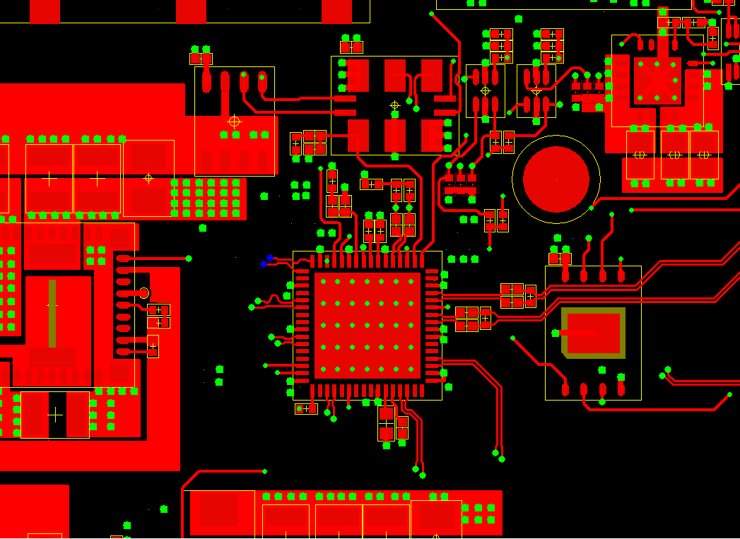
    Can you share your PCB layout and stackup details for us to review?

    Alan
  • Alan, Patrick,

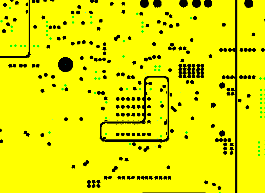
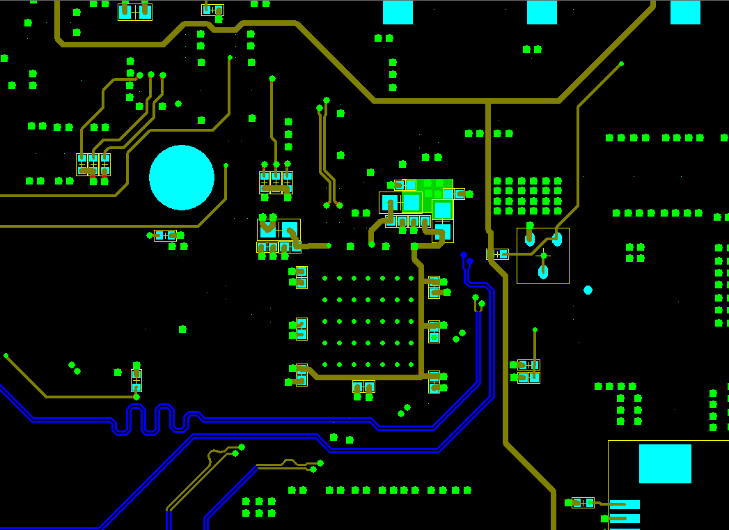
    here is a top-view of the LMK04806 on the PCB (top elec):

    +3.3V is located on Layer 8. The small extra-Plane is 3V3_0:

    And here is Bottom-Elec with some Power-supply filters:

    The Layer-Stack is composed of 16 layers as follows:
    (1) Signal + Placement (Top Elec)
    (2) Ground
    (3) Signal
    (4) Signal
    (5) Ground
    (6) Power
    (7) Ground
    (8) Power
    (9) Ground
    (10) Signal
    (11) Signal
    (12) Ground
    (13) Signal
    (14) Signal
    (15) Ground
    (16) Signal + Placement (Bottom Elec)

    Regards,
    Niels

  • Hello Alan and Patrick,

    it's a few days now since we last talked about this topic.

    As I have no other ideas, I would like to ask you if you could be so kind to calculate the PLL1 and PLL2 loop-filters for me.
    The focal point during should be on a most stable operation of the loop, leading to "maximum lock capability".

    I am looking forward to your answer.

    Regards,
    Niels

  • Hello all,

    by luck, I recognized that the optimal loop filter design depends on the phase noise of the input clock.

    So I played a while with several different input clock phase noises to get a feeling how this influences the loop filter. The "Clock Design Tool" is quite a nice tool for this task, but setting the correct phase noise should be more visible.This could have saved me some weeks.

    In my actual configuration, I used the following loop filter:
    PLL1: 10nF || 47k + 2200nF     (10kHz PDF, 1.6mA CPout1)
    PLL2: 1nF || 100R + 220nF      (150MHz PDF, 3.2mA CPout2)

    With these loop filters, the LMK04806 locks in "dual PLL, Int VCO, 0-delay mode".

    Bye,
    Niels