This thread has been locked.

If you have a related question, please click the "Ask a related question" button in the top right corner. The newly created question will be automatically linked to this question.

LMX2571 Lock Problem with MULT Setting

Other Parts Discussed in Thread: LMX2571, CODELOADER

Hello,

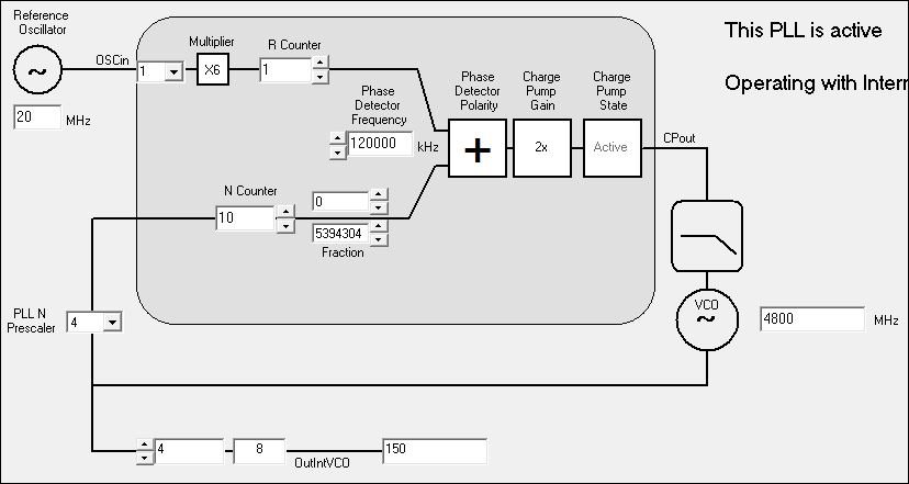
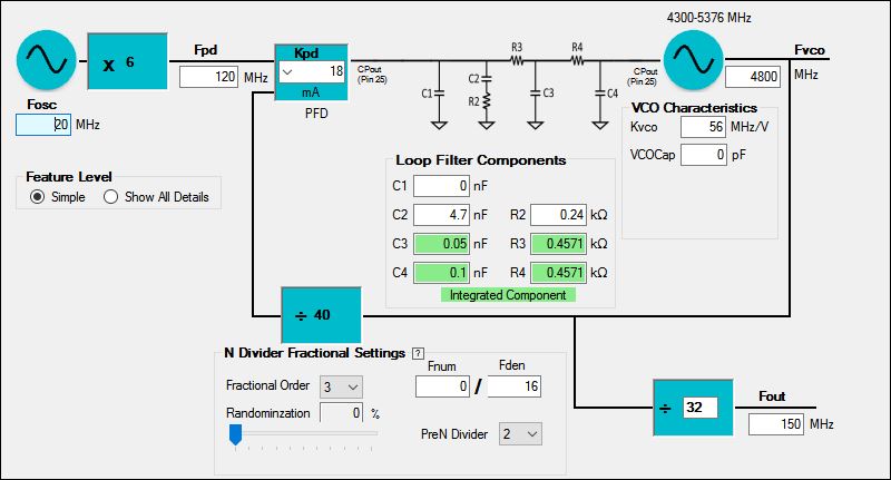
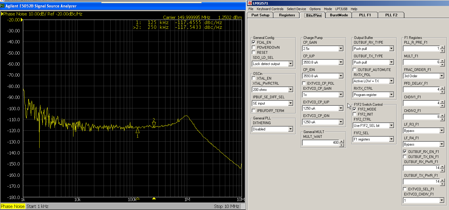
I am trying to implement FM transmitter using SPI Fast Mode in LMX2571. I need to play with MULT value in order to set a proper max FM deviation. For this purpose I should set MULT = 6 with fOSCin = 20MHz. Both Predivider and postdivider values are set 1. So I will have fPD = 120MHz. But it doesn't work in this setup, PLL did not lock and there was no RF signal at tx out. Same problem applies with MULT = 5. I can only make it work with MULT = 4 so fPD = 80MHz. What could be the reason?


In the datasheet, MULTin and MULTout ranges are given and my setup fits those. By the way, I have tried this in the evaluation board and also custom board that we have done for our application. Both cards use the same clock generator. I have ordered 100 and 125MHz clock generators to test the same setup by setting MULT = 1. I have also 40MHz clock generator to use.

What could you suggest to me? I appreciate your help.


My best,

-

UT

  • Hi Ufuk,

    We received your question. Thank you for your interest in our products. I forwarded your query to the applications engineer most familiar with this device.

    Best Regards,
    Julian
  • Hi Ufuk,
    Would you provide screen shots of your configuration?
  • Hi Noel,

    Sure. I have put it below. I also put the loop filter characteristics of the custom board.

    As I said before, I have also tried the same setup with evaluation board with its own loop filter circuit given in the datasheet. I used different charge pump current values and nothing changed.

    I am waiting for your reply.

    Best,

    -

    UT

  • Hi Ufukt,

    Please check if you have setup properly on the "Bits/pins" tab. I can make it lock without changing the loop filter except R3, R4 have to be configured to Bypass.

  • Hi Noel,


    Thank you for the reply. I have worked on this today and I realized some different things on LMX2571. With your setting, I could also make it lock by using evaluation board with code loader. And then I tried this with microcontroller and everything was fine. But when I tried different frequency like 140MHz. It failed and did not work. Once I was trying to make it lock. I have figured out that if PLL is locked with some setting ( say for example with MULT = 4 ) you can make it lock with MULT = 6 succesfully after locked with MULT = 4. I had tested my operating freqeuncy band with MULT = 4 and it had worked succesfully for all channels. Hence I changed my code in microcontroller so it first locks with the setting MULT = 4 and then it sets MULT = 6 and locks in the desired channel. This is interesting but it worked in my application. Still I am wondering why is that so and can it be better solution for my application?

    Thank you for the service,

    My best,

    -
    Ufuk
  • Hi Ufuk,
    Whenever you change the PLL settings (except for output dividers, they are outside the loop), you need to calibrate the internal VCO by sending R0 with FCAL_EN=1. For example, if you are locking to 480MHz and then you want to lock to 520MHz so you program a new N-counter value. If you stop here, the PLL will not lock because the VCO is not calibrated. Now, program R0 again (assume you already have FCAL_EN=1) and you will get it locked.
  • Hi Noel,

    I knew what you have suggested to me. In my frequency setting, if MULT and N counter values are changed, registers are programmed in order (first R6 and then R4 and lastly R0 with FCAL_EN = 1). However, even in this situation, I cannot make PLL locked to the 140MHz with your suggested settings. The interesting thing is that I can make it work, if I first lock 140MHz with MULT = 4, it locks and then I reprogrammed with MULT = 6, and correspongind Ncounter and lastly R0 with calibration enabled. I learned that PLL locks everywhere in my operation band (between 130-180MHz) with MULT = 4, however it does not work with MULT = 6. But if you first lock PLL with MULT=4 to the frequency where it does not work with MULT= 6 and then change MULT it keeps locked. Is this result reasonable or do I make some wrong operations? Does this PLL has to lock in my operation frequency band with MULT = 6 directly just by changing the corresponding N counter and calibration enabled ?

    As I said you before, all frequency settings are programmed to the registers in order and R0 is programmed lastly with calibration enabled.

    Best,
  • Hi Ufukt,

    Would you advise which frequencies you cannot lock with MULT=6? I would like to give it a trial.

  • Hi Noel,

    As I said before, for example, I cannot make it lock at 140MHz. I tried both lower frequencies like 136MHz and upper frequencies (145MHz) and all of them were failed.

    However, with the same loop filter settings, if the PLL is locked first with MULT=4 and then locked with MULT = 6. It is locked in all frequency band of interest.
  • Hi Ufuk,

    Please try with Prescaler equals 2, it should work now.
  • Hi Noel,

    Prescaler should be set to 4 in my application to obtain desired maximum fm deviation. Otherwise I will get half of it. Actually, I can make PLL locked in all frequency band of interest with my method even when Prescaler = 4 (first lock with MULT = 4 and then lock with MULT = 6). But this is very interesting and I have no idea why this works?
  • You can also try what I did. Simply when using codeloader, first lock the desired frequency with MULT = 4 and then change MULT = 6 and load device again. PLL will lock to the desired frequency. If you had tried directly with MULT = 6, it wouldn't work.

  • Hi Ufuk,

    OK, if Prescaler has to be equal to 4, then you have to set a hidden register bit. Put R0[4] = 1, you shall be able to make it lock in one hit.
  • Hi Noel,

    Thank you for the reply. It is really interesting that your suggestion works successfully. Could you explain it more about setting this hidden register bit high? What does it actually do? Is there any trade-off using this bit (any disadvantage)?

    Since I can make it work without using that bit by manipulating in software.

    Best,
  • Hi Ufuk,

    This bit is used to reduce the fpd to half during VCO calibration, it is applicable when fpd is very high and there will not be any side effect.
    In fact, I am considering to disclose this bit in next datasheet revision.
  • Hi Noel,

    Thank you for the explanation. I am looking forward to next revision for any other updates.

    Best,