This thread has been locked.

If you have a related question, please click the "Ask a related question" button in the top right corner. The newly created question will be automatically linked to this question.

TLC551: Glitchy override sequence whenever Trigger pin low while Threshold pin high, while at sub 1.3 Vdd

Part Number: TLC551

Hello,

On the TLC551, the output is showing low while the Trig pin is low, and the Thresh pin is high, but the Trig is supposed to override Thresh. This problem usually occurs while operating the device at Vdd below 1.3V, although sometimes at higher voltages. All measurements are taken upon initial power-up of Vdd with a slew rate of about 1V/us; sometimes faster. Reset is tied to Vdd, and the behavior persists with or without manipulation of the Control pin.

At 1.3V Vdd, with the Trig pin and Thresh pin capacitively coupled to GND and Vdd respectively(12nF both), the output undesirably goes low. If only the GND coupling cap is replaced with a dead short to ground, the output successfully stays high. However, even with the dead short in place, when Vdd is lowered to 1.1V, the output again undesirably goes low. EMI effects have been observed, but the phenomenon persists even when partially addressed. It is important for this application that the output initially be high, and stay that way at least until Trig is pulled above it's trigger voltage. The pin priority of Trig overriding Thresh is an important property to preserve. If Trig and Pin are tied together, and then coupled to GND , the output successfully goes high. However, tying them together is not the desired arrangement. 

Any thoughts, solutions? It is desirable to avoid placing any parts in the path of the main branch of the positive supply rail. 

Thanks

  • Pongo,

    Is the control voltage (pin 5) at 2/3 VCC when this happens?
    For bipolar 555 family of devices, trigger always overrides threshold. In CMOS 555 family of devices, this is also true if pin 5 is close to 2/3V VCC (or higher). Removing the pin 5 capacitor should be sufficient to solve this startup issue.
  • Hey Ron,

    Yes, it still happens when CONT pin is higher than 2/3 Vcc.

    I removed the CONT pin capacitor long ago, but have tried variations coupling it to GND or to Vdd. At 1V Vdd, if I couple the CONT pin to Vdd through a small capacitor(2nF - 12nF), the problem is only delayed. It still happens, but only after some time constant while CONT approaches a steady state voltage. So you can see, the issue reappears even some time after start-up(after several hundred microseconds).
  • Pongo,

    I will test TLC551 samples to see how trigger override behaves including power up rates and low Vdd voltage.
    Can you tell me more about the meaning for "GND coupling cap" Is pin 1 not grounded?
    Can you tell me more about the meaning for "EMI effects"?
  • Pongo,

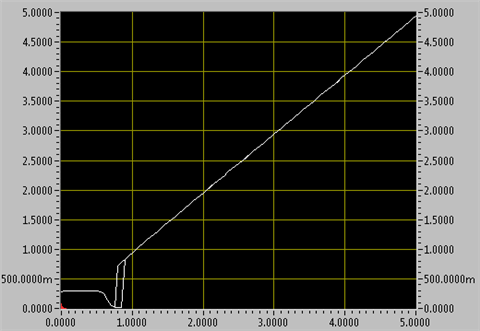
    First I tested VDD sweep when trigger=0V, threshold=VDD. OUT 25k to 0.3V (to see HI-Z operation)

    OUT is not high nor high impedance for the range between 0.6V to 0.9V

    Then I tested OUT vs. CONT when VDD=1V (no load)

    So CONT must be at least 0.4V (at VDD=1V) for desired OUT high.

    Then I tested a full range on VDD rise times and the only certain OUT high for the full power on event required CONT to be high (tied to VDD) and I also has a pull up resistor to VDD for VDD range were output is not yet functioning  (High impedance).

    Lastly I tested OUT vs.VDD sweep again except this time CONT was tied to VDD. OUT has 25k to VDD

    This is the desired result. OUT high the whole time.

    It is not practical to short CONT to VDD, however a capacitor from VDD to CONT should provide the same benefit.

  • Hello Ron,
    Thanks for doing that testing. It confirms a lot of what I've been seeing. I will respond to both of your posts, one from the 19th, and the other data rich post from the 20th.

    You said:
    "It is not practical to short CONT to VDD, however a capacitor from VDD to CONT should provide the same benefit"
    My comment:
    --All at 1V Vdd, and "false trigger" here refers to output going low while TRIG is also low--
    I have previously found that coupling CONT pin to Vdd with a capacitor alleviates the problem for short rise times on Vdd, but that the problem reappears for the slower rise times on Vdd. In application, the circuit will be encountering longer Vdd rise times as well. Increasing the CONT-to-Vdd cap helps with longer rise times at Vdd, but slows down the chip's response to subsequent inputs, which is not desirable. Tying CONT to Vdd through a medium valued resistor helps in some cases, but if TRIG is coupled to GND through a small capacitor(12nF, sometimes larger) rather than shorted or switched to GND as in your tests, then the problem reappears. Note, when tying CONT to Vdd through a resistor, I was forced to go beyond the recommended 80% of Vdd and approach 85-90% to obtain better results. Switching CONT high through a transistor has had the best results. This echoes your comment of shorting CONT high. There just happened to be a usable signal for me to test this with, but for other reasons using a transistor to switch CONT high is not an ideal solution.
    Also, when used in combination with another TLC551 timer, providing an independent CONT signal for each chip greatly reduces the amount of false triggers. When two or more CONT pins are tied together, I almost always get false trigger events. A larger cap from CONT to Vdd helps, but as previously stated this isn't feasible for me.

    On Dec 19th you asked:
    "Can you tell me more about the meaning for "GND coupling cap" Is pin 1 not grounded?"
    My comment:
    Pin 1 is always directly shorted to ground.

    On Dec19th you asked:
    "Can you tell me more about the meaning for "EMI effects"?"
    My comment:
    What I observed was that the output was picking up low frequency ambient noise, and that this was affecting the chips behavior. The affect was that the false triggering was random when this noise was present. After beefing up the ground plane, the low frequency noise disappeared, and the false triggering became consistent. However(Haha, getting high tech now)when I place my finger on the output, the amount false triggering greatly decreased. It was observed that when placing a finger on the output, a small amount of negative bias(250mV or so) was present at the output that resulted in improved performance.
  • Pongo,

    Undesired power up / down behavior is usually solved by added under voltage lockout circuit.
    Can you share more details about the desired operation of the TLC551 timer in normal VCC operation?
    I ask because over 90% of timer apps do not asser TRIG and THRES at the same time.
  • Hey Ron,

    The Trig and Thresh pins are out of phase set by a different timer circuit. The Trig pin proceeds the Thresh pin in the sequence. When the Trig pin is low, the TLC551 output should go high regardless of Thresh state. When the Trig pin goes high, the TLC551 output should stay high until the lagging Thresh pin goes sufficiently high. All switching is rail to rail. Switching levels are set by the CONT pin which is set by diodes and a transistor to keep CONT appropriately close to Vcc regardless of Vcc levels. You can probably see that this setup is close to(but not exactly the same) as a NAND gate whose voltage levels are set with a CONT pin instead of standard hysteresis. So if you have a nice NAND gate or equivalent with 1V-10+V operation. Please let me know.

    Until a better solution is revealed, I'm switching the CONT pin high during startup with a transistor to avoid some of the false triggering.

    What type of lockout circuit are you suggesting? If you recall from my first of these posts, I mentioned that placing devices in the path of the main rail is not desirable, but not out of the question. An example might be a p-channel mosfet with its gate connected to the output of a comparator monitoring Vcc levels.

    Regardless, I am interested to hear any solutions which you may have for the TLC551, or lockout solutions whatever they may look like. Low Vdd capable devices such as the 1V of the TLC551 are preferred, and higher Vdd max of at least 10V is necessary.

    Thanks and Happy Holidays
  • Pongo,

    I didn't find a logic alternative that supports 1V and 10V, so TLC551 is the best choice.

    Lockout as I see it, would simply hold output in fail safe state (static low or high, your choice) until VDD was above a minimum voltage for a short time.