This thread has been locked.

If you have a related question, please click the "Ask a related question" button in the top right corner. The newly created question will be automatically linked to this question.

NE555: NE555 generate single pulse

Part Number: NE555

The application is that once received a triggering signal, the circuit will generate a pulse with preset pulse width. I applied NE555DR timer to generate the pulse and digital potential meter to tune the pulse width.

The design is attached below.

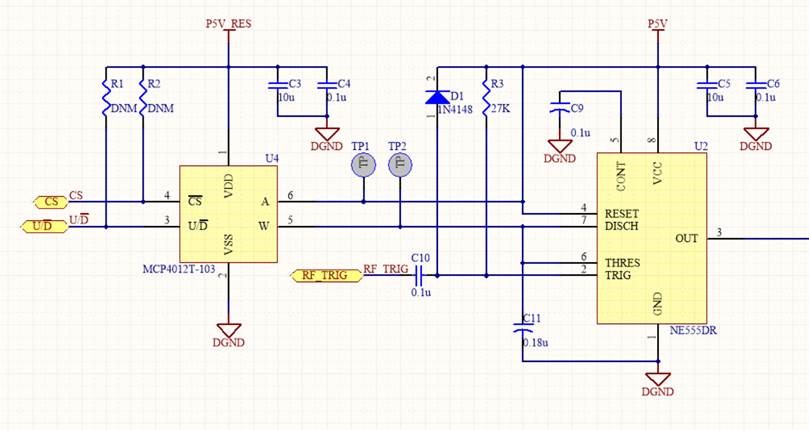
The problem is before the NE555DR  is mounted on the PCB, the MCP4012T-103 digital potential meter is functional, and I can measure the resistance on TP1 and TP2. However, after I mount the 555 timer on the PCB, the resistance of MCP4012T-103 becomes infinity and no output from NE555DR. Could you help to check what is wrong of my circuit? How do I improve it?

  • Hello ZHAONIAN,

    One possibility is that the MCP4012 is being damaged when P5V supply is on and P5V_RES supply is off. This would directly apply 5V to terminal A which would exceed VDD pin. I suggest adding a resistor between 5V and terminal A to also help prevent high current flow if Dpot sets wiper all the way to A.

    When there is no timer output what is the voltages (or waveforms) on the NE555 timer pins?

  • Dear Ronald Michallick,

    Thanks for your reply.

    According to MCP4012 datasheet, the maximum operating voltage is 5.5V and the maximum voltage on resistor terminal is also 5.5V. Moreover, there is a 5V trace connected to terminal A on PCB. Even the 555 timer is not mounted on PCB, There is still a 5V supply on terminal A. Without 555 timer, the MCP4012 is working properly. The MCP4012 is not functional only when 555 timer is mounted.

    Thanks!

    Best Regards!

    Guo Zhaonian 

  • Guo Zhaonian,

    The NE555 timer follows simple rules in this priority

    1) If Reset pin is low, the output will be low. Schematic say 5V, but measure it anyway.

    2) If Trigger pin is low, the output will be high. Please measure trigger voltage. 

    3) If Threshold pin is high, the output will be low. Please measure threshold voltage.  

    4) Keep output the same. You did not mention if output is always high or always low.