This thread has been locked.

If you have a related question, please click the "Ask a related question" button in the top right corner. The newly created question will be automatically linked to this question.

TPL5110: TPL5110 One button on and off

Part Number: TPL5110
Other Parts Discussed in Thread: TPL5111, SN74LVC1G11, SN74LVC1G80, SN74LVC1G3157

Hello.


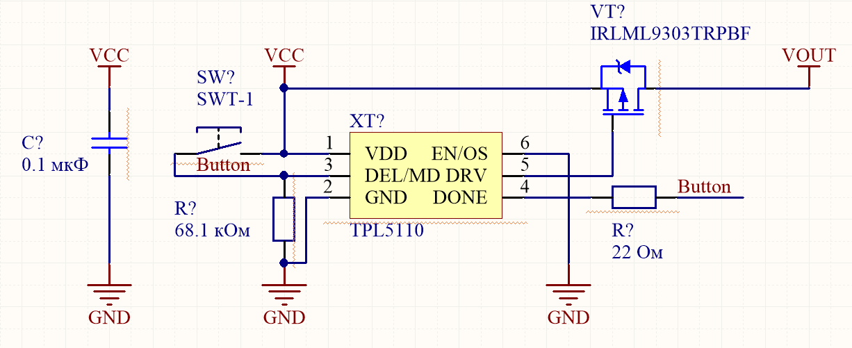
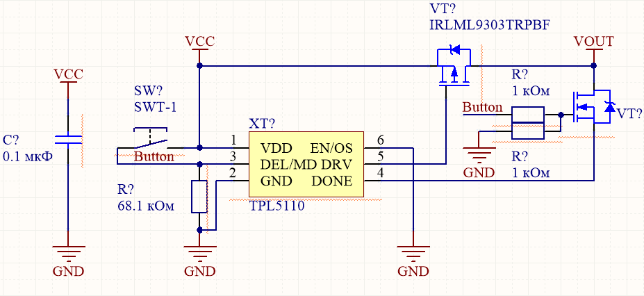
Please tell me if the circuits are designed correctly
In Figure 1, I would like to design the TPL5110 to start a timer by pressing a button for 15 minutes, and shutdown by pressing the same button when the transistor is on, the DELAY /
M_DRV is not active. Will the circuit below work? will there be a problem when starting the timer when the button is pressed, since a high level will come to the DELAY / pins
M_DRV and DONE (do you need a 22 ohm resistor)?
There is a second implementation of this circuit shown in Figure 2

Figure 1

Figure 2

  • Hello Ildar,

    Per section 7.5.2.1 of the TPL5110 datasheet, DONE signals received while the DELAY/M_DRV is HIGH are ignored. Neither circuit would successfully disable VOUT; instead, pressing the button would reset the counters, extending the duration of VOUT=HIGH by ~15 minutes. Additional logic would be required to create the multi-state configuration you describe.

    Both DELAY/M_DRV and DONE pins can be directly driven from VDD/VOUT, and do not require any damping resistor.

    Regards,

  • Thanks for the answer, please tell me more

    Is there a timer in your line that could perform the function of turning on and off at the touch of a button?
    Can you suggest what kind of logic might be added to this circuit?

  • Hi Ildar,

    To my knowledge there isn't a TI timer which has the specified toggle function.

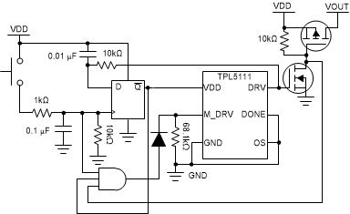
    A simple option would be to use a TPL5111 (same as TPL5110, but DRV polarity inverted) and a D-flip-flop to act as a toggle control for powering the timer. If the button is pressed while the timer is active and DRV is high, the DFF state switches low, the timer shuts down, and power delivery is halted. If the button is pressed while the timer is powered down and DRV is low, the DFF state switches high, power would be restored to the timer. and it would begin operating for 15 minutes. And if the button is pressed while the timer is powered and completed, the DFF state does not change, but the combination of power the timer, deactivated power delivery FET, and button press reactiviates M_DRV. The 0.01µF capacitor sets the initial state on the DFF, but this could also be accomplished using a device with asynchronous preset/clear and an RC circuit. I have also drawn the circuit with button debouncing, since the inputs are applied to devices other than the timer. An example DFF device which could be used is the SN74LVC1G80; an example 3-input and gate is the SN74LVC1G11.

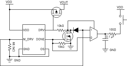
    An alternative implementation uses a demux and some open-collector logic to accomplish a similar result on TPL5110. If the button is pressed while the timer is active, the demux is set to path 0, which applies VDD to the DONE input causing DRV to go high. As long as VDD remains on the DONE pin, the N-channel MOSFET will lock the demux on path 0. When the button is released, the demux transitions to path 1 through the 10kΩ to DRV. When the button is pressed while the timer is complete, a signal is applied to M_DRV to trigger a manual one-shot, and DRV is pulled low. As long as VDD remains on the M_DRV pin, the diode will lock the demux on path 1. When the button is released, the demux transitions to path 0 through the 10kΩ to DRV. And if the timer expires naturally, the demux is set to path 1 through 10kΩ by the DRV pin. Again, switch debouncinig is presented to help maintain the state on the demux, but the 100Ω could be replaced with a diode. An example demux IC which could be used is the SN74LVC1G3157.

    Conceptually, your requirements form a three-state system. You can draw out the states and the state transition diagram, identify the required conditions, and draft some circuit of your own as well. There is likely a lower cost or lower component count implementation of the circuit, but this is a good first pass to get you started.

    Regards,