This thread has been locked.

If you have a related question, please click the "Ask a related question" button in the top right corner. The newly created question will be automatically linked to this question.

BQ4802LY: CSIN pin

Part Number: BQ4802LY
Other Parts Discussed in Thread: BQ4802Y

Hi All,


I have a question about BQ4802.

Is access disabled when Low is input to the CSIN pin?
The CSIN pin is a chip select pin.
Can CSIN control enabling and disabling access to the RTC?


Best Regards,
Ishiwata

  • Hi Shuji,

    The chip select pin CS is active low, or /CS, shown in the data sheet with an over bar.  When high it prevents access.  When low it enables access. See table 1 in the BQ4802LY data sheet.

  • Hi


    Thank you for your reply.

    I made a further mistake.
    I wanted to hear about CEIN, not CS.

    Is access disabled when High is input to the CEIN pin?

    I understand that entering High in CEIN disables access.

    I have additional questions.

    If VCC <BC, will the following specifications be VBC instead of VCC?

    VCC> BC: Input high voltage, VIH  = 2.2V (min) / VCC + 0.3V (max)
    VCC <BC: Input high voltage, VIH  = 2.2V (min) / VBC + 0.3V (max)

    Do you have this recognition?

    Also, is the amplitude of oscillation of the crystal unit in the range of VIL and VIH?


    Best Regards,
    Ishiwata

  • Hi Ishiwata,

    CEIN from its general description would seem to disable access if it were inactive = high.  It is not shown as a condition for read or write, Table 1 shows CEIN as a condition for CEOUT, but not for other functions. The system diagram and descriptions seem to indicate that CEIN is processed with the power conditions to CEOUT for the SRAM rather than for internal use.  I have not used the part and an EVM is not available, so I can't confirm if CEIN will block access to the BQ4802 registers.

    If VCC < BC, the specification for input is still given with respect to VCC.  Inputs will use the supply voltage, not the battery back up supply which would be used only for back up.  The inputs would generally be powered from VCC.  As VCC falls the input level will fall also.  The threshold circuits do have a minimum for proper operation, and of course the access protection of the IC. Beyond that general implementation I don't have specific experience on this IC.

    Again I don't have specific experience with this IC, but typically the amplitude of the crystal circuit will be lower than the VIL, VIH levels.  When the crystal is not used and a 32.768-kHz waveform is fed into X1, it should meet the VIL, VIH levels.

  • Hi

    Thank you for your reply and answer.

    I understand.

    I have additional questions.

    Turn off VCC so that it is battery-powered.
    At that time, input High of the battery power supply to the CS pin.
    At this time, the standby mode is set.
    I want to put it in battery backup mode.
    How do I set it if I want to put it in battery backup mode?


    Best Regards,
    Ishiwata

  • Hi Ishiwata,

    While it is not specifically stated, the general expectation is that VCC supplies the IC power as well as the interface circuitry which drives the address, data and control lines.  When VCC goes low, CS would also go low.

    The ABS MAX does not show a limit for the inputs with respect to VCC.  The recommended level for VIH has a maximum of VCC + 0.3V.  It is likely that there is a diode between CS and VCC so that if CS is held high while VCC is removed, CS will provide power to VCC and hold up the voltage. This is not a recommended mode of operation.

    To put the part in battery backup mode:  Turn off VCC and the drivers for the input signals.

  • Hi


    Thank you for your reply.
    I understand in your answer.

    I'm sorry many times.
    I have additional questions.


    If SRAM is not connected, are there any restrictions on the timing of the CEIN input signal?
    Please let me know if there are any restrictions.

    Also, if you do not use WatchDog, there is a description that WDI pin is floating.
    Is it necessary to pull up because it is an input pin?
    Or is it pulled up internal?


    Best Regards,
    Ishiwata

  • Hi Ishiwata,

    The part is an older device with limited information and no EVM for trials.  I must rely on the data sheet.

    CEIN and CEOUT are described with respect to the external SRAM.  They do not seem to have a function related to access of the RTC or supervisor function registers.  Note in table 1 the CEIN state is not a condition for read or write.  CEIN is an input, if the SRAM is not used it should be held at a defined state.  The electrical characteristics table does not show a dependency on its state so either level could be used.

    If the WatchDog feature is not used the WDI pin should be left unconnected.  It will be held at an internally regulated voltage, this is by design, see the description in the Terminal Functions table and in the second paragraph in the "Watchdog Input" section. 

  • Hi All,


    Thank you for your reply.

    I have additional questions.

    If it does not use each of the pins below, which is Open or Pull-up / Pull-down?


    - /RST pin
    - VOUT pin
    - /CEOUT pin
    - /WDO pin


    For /RST pin, communication was unstable when it was Open.
    When I pulled up /RST, the communication became stable.
    Do you know the reason for this?


    Best Regards,
    Ishiwata

  • Hi Ishiwata,

    Please see the data sheet Terminal Functions table, diagrams, and descriptions.

    -/RST is both an input and an output, it should have a pull up.  The Electrical Characteristics table note 1 indicates it is open drain, but there are also  levels for the push button voltages and the Terminal Function entry describes it having a reset cycle.

    -VOUT is the output voltage for the SRAM.  If not used it can be left open

    -/CEOUT pin is an output pin for the SRAM. If not used it can be left open

    -/WDO pin is an output intended to go to the MCU as an interrupt.  If not used it can be left open.

    Since RST has an input function it should have a pull up as shown on the page 1 schematic. If operated without a pull up the pin may drift low and stop communication.


  • Hi All,


    Thank you for your reply.

    I have additional questions.

    /RST is both input and output, Does /RST check the status of the output reset signal by itself?
    Is there such a feature?

    Also, is it possible to get a block diagram of the internal circuit of the / RST pin?


    Best Regards,
    Ishiwata

  • Hi Ishiwata,

    Yes, since the /RST is both input and output it must have some method to prevent it from latching.  The data sheet does not describe the method in detail, but the figure 10 and description in the Terminal Function table "... enters the reset cycle when RST is released from being pulled low for more than 1 µs" indicate the input function is a rising edge detection and the part would know if it was releasing the output. 

    No other diagram is known other than the one in the data sheet. 

  • Hi All,


    Thank you for your reply.

    I have additional questions.

    There are reports that BVF is always changing.
    Is this because / RST hasn't been pulled up?
    Or are there other factors?


    Is it possible to detect a low voltage (2.1V or less) and flag the BVF?
    Also, can the flag kept until the next write time after detecting a low voltage?

    I have a question about the current consumption of the BC terminal.
    Please tell me the ICCB(Battery operation supply current) at Ta = 65 ℃ when VCC is supplied and operating.


    Best Regards,
    Ishiwata

  • Hi Ishiwata,

    The data sheet indicates BC is tested at start up.  It does not say that it is not updated.  If BVF is changing and the part is not in the BC threshold region floating /RST could be the cause since it would cause repeated start ups. The part is intended to have /RST pulled up.

    Yes low voltage is detected by BVF as described in the data sheet.  It is not specified if it is latched or not, the BATTERY–LOW WARNING section indicates "The bq4802Y/bq4802LY checks the battery on power-up."  Once adequate VCC is present the part will operate from VCC, it does not say if it is updated or not.

    The ICCB is not characterized separately in the conditions you specify.  Supply currents are only specified at 25C.


  • Hi All,


    Thank you for your reply.
    I have additional questions.

    When VCC = 3.3V, there was almost no current consumption at the BC pin.
    Is this because the BC pin is in the open state because VCC> BC?
    If VCC> BC, power is supplied at VCC, so it switches.
    Therefore, the BC pin is understood to be in the Open state. Is this understanding correct?

    Also, is it the order that after 3.3V is applied to VCC (VCC> BC), the voltage of the BC pin is seen and reflected in BVF?
    As an example, will the BVF change if the battery voltage drops below 2.1V for some reason when operating at VCC?


    Best Regards,
    Ishiwata

  • Hi Ishiwata,

    The BC pin has little load when VCC is present, it is basically switched off.  While the circuit is still there BC is not providing current so considering it open is ok for understanding.

    The BATTERY–LOW WARNING section in the BQ4802LY data sheet says the battery is checked at reset.  Reset would normally be when VCC is applied after it has been off for some time.  The system does not know if the battery has been operating a long time or a short time, so a check at this point is important.  The same argument may be made for operation, if the system has been operating for some years the battery may have gone bad, but the data sheet does not describe that the check is done on change of BC voltage. If you have a working system you might try a reset to see if a BC check is done on reset.  VCC causes reset, but the data sheet does not indicate whether BVF check is VCC or reset initiated.   

  • Hi All,


    Thank you for your reply.
    I have additional questions.


    What are the expected uses for BVF?

    Even if you detect the BVF flag at VCC startup or reset,
    " It is not specified if it is latched or not " you replied.
    If it doesn't latch, there is no time to read the flag, how do you read the flag?


    Best Regards,
    Ishiwata

  • Hi Ishiwata,

    My choice of words was poor.  BVF is latched at reset.  The MCU can read the flag whenever it wants.  The expected use is that the system wakes up, the MCU reads the date and BVF flag.  If BVF is 1 it can trust the date.  If BVF is 0, the MCU knows that the battery is low and that the date it read may not be correct, it can ask the user for a new date and to replace the battery. 

    The data sheet does not say if the BVF is updated (latched) during operation.  For example if the system starts and operates for some time, perhaps minutes, hours, days or years.  During that time the BC voltage drops below 2.1V, perhaps the user removes the battery.  It is not stated if the BVF is updated.  There is no reason for BVF to be updated since the system has the VCC power available to run the clock and time is not lost.  So the MCU can't read BVF to tell the user that they should replace the battery.  The next time the user starts the system the MCU would read the BVF flag as 0 and can tell the user to replace the battery and set the time. 

  • Hi All,

    Thank you for your reply.
    I have additional questions.

    Is the reset of BVF the period when /RST in Figure 9 of datasheet is outputting Low?
    Also, when the BVF flag becomes 0, replace the battery to make it 2.1V or higher. And does it hold 0 even when the power is turned on?
    Is the only way to set BVF to 1 is to write 1 from the MCU side? Is there any other way to change the BVF from 0 to 1?

    Best Regards,
    Ishiwata

  • Hi Ishiwata,

    The BQ4802 data sheet does not specify where in time the BVF is set other than "on power-up"   Since the bit is intended to be read by the MCU it is good to expect it is established before /RST goes high at power up.

    Since changing the battery is an infrequent operation in the concept of the part and the data sheet does not indicate an additional condition for the BVF bit update, it is likely that the VCC power-up during reset is required for the part to update the bit. It likely holds as 0 until power is turned off and on.

    The data sheet does not describe how BVF is changed other than the power-up check.  It is not identified as a read-only register so it may be possible to write it. 

  • Hi All

    I am very grateful for your answer.

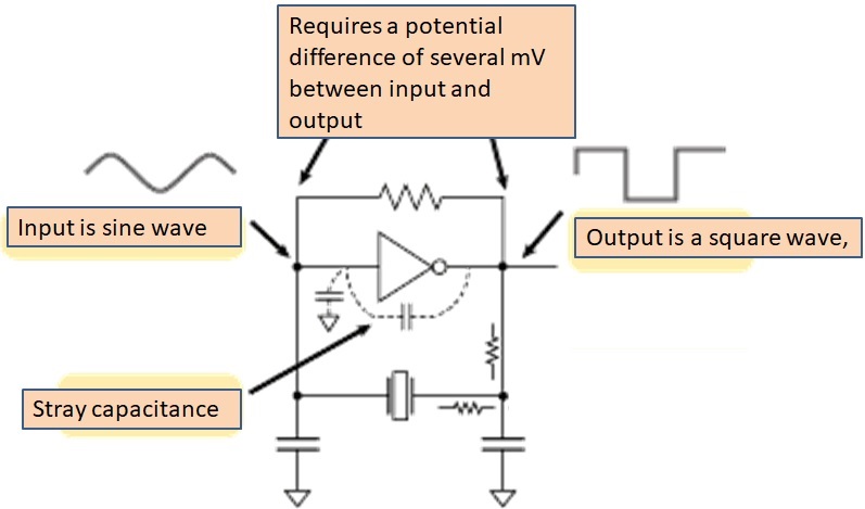
    I have a question about the X2 pin.

    What is the expected value of the amplitude level output to X2 pin?
    What kind of output waveform can you expect?

    Also, regarding the internal circuit of X2, I understand that it has the following structure.
    Is my understanding correct?


    Is there a feedback resistor inside the IC?


    Best Regards,
    Ishiwata

  • Hi Ishiwata,

    The data sheet does not detail the oscillator design or operation and no additional information is available.  Your sketch is typical of oscillators.  X2 is marked the output and would be the square wave signal, X1 is the input.  Note that the oscillator has a feature to stop, it will have some additional feature beyond your sketch, see the data sheet section "STOPPING AND STARTING THE CLOCK OSCILLATOR"