This thread has been locked.

If you have a related question, please click the "Ask a related question" button in the top right corner. The newly created question will be automatically linked to this question.

LMX2541: output has harmonics and frequency stable questions

Part Number: LMX2541

Hello,

I have some questions about LMX2541, when configured 500Mhz output, the FTEST/LD could be pulled high successfully, but the output waveform has harmonics。

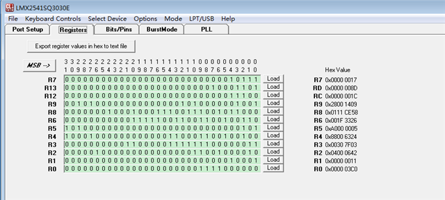
The configuration is as following:

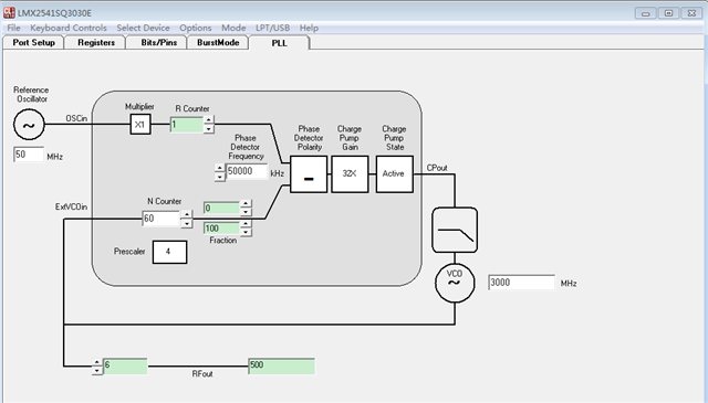
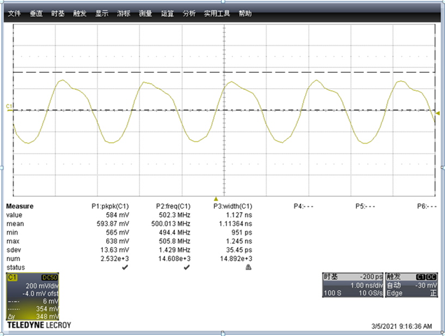
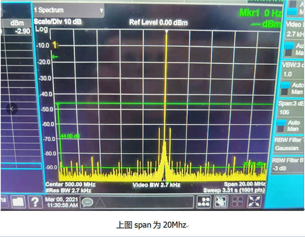
Question 1:The 500Mhz output waveform is tested as this, we could find that it is abnormal.  Why? 


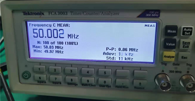
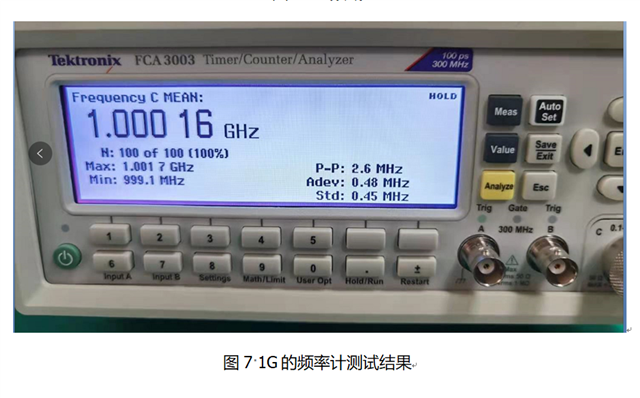
Question 2: When used frequency meter to test the 500Mhz output, and sample time is 200ns,P-P is 0.9Mhz, and we could find that the std=0.18Mhz  is a little big. Is it normal? 

 While the clock source is as this:

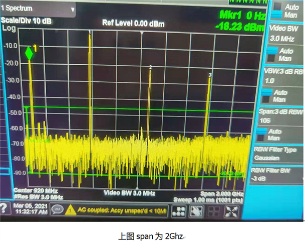
Question3; When tested the 500Mhz output with spectrum, we find that it would appear harmonics with 1G and 1.5Ghz frequency. If changed the clock source with signal generator, it would also appear harmonics, so the harmonics has no relation with clock source, how to generate the harmonics?

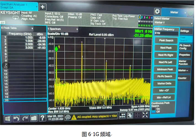
Question 4: If we changed the divider from 6 to 3,and output 1Ghz clock, and with the same tested condition, we could find that the output waveform is better than 500Mhz output. And we tested with frequency spectrum, it also has 2G,3G harmonics, but the harmonic amplitude is lower than 500Mhz.

So why the performance is better with higher frequency? Does it has any other design consideration? 


Best regards

Kailyn

  • Hi Kailyn,

    Q1

    What is the bandwidth and sample rate of their oscilloscope? Were they using a probe to take the waveform or connect the output to the scope with a coaxial cable? What was the input impedance setting of the scope?

    If the scope is setup correct, I expect they will see a 500MHz square wave clock. This is because the output divider is a counter, its output is therefore a square wave, especially when the output frequency is low. if the bandwidth of the scope and probe is not high enough, the measured waveform will distort. 

    Q2

    If I read their data correct, their reference clock frequency varies between 50.03MHz and 49.97MHz. The synthesizer multiplies this clock 10 times to 500MHz. So the output frequency will vary between 500.3MHz and 499.7MHz.

    Q3

    There is no filter after the output divider, so it is very normal that there will be harmonics at the output.

    Q4

    Same as Q1, the measured waveform depends on the test equipment capability and setup. In addition, at higher output frequency, the output divider's parasitic capacitance will round-off the edges of the output signal. As a result, the output signal waveform will has a slower edge rate. In frequency domain, that means the harmonics are smaller. 

  • Hi Noel,

    Thank you very much for your reply.

    Q1:The bandwidth of the oscilloscope is 1GHz, and the sample rate is 10Gsps. He used the coaxial cable, and jumped wire  to connect the red circle of the above schematic . The input impedance of the oscilloscope is 50ohm.So the setting of the oscilloscope should be no problem. Does the jumper wire of the coaxial cable cause the harmonics?

     
    Q3:Does the LMX25413030EVAL appear the harmonics with 500MHz output? What is the offset(dB) between harmonics and dominant frequency? If there is any other solution to decrease the harmonics of the EVM board?

  • Hi Kailyn,

    If the question of this post is to look for a solution to reduce harmonics of a 500MHz output, then the answer is use external low pass filter. The synthesizer does not include any circuitry to filter the output. Datasheet said 2nd harmonics is about -20dBc.