This thread has been locked.

If you have a related question, please click the "Ask a related question" button in the top right corner. The newly created question will be automatically linked to this question.

ADS1258EVM-PDK: use ads1258 with bipolar config

Part Number: ADS1258EVM-PDK

Hi,

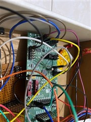
I was using the ADS1258EVM

Currently it is working on 5V supply with reference of 1V and I am nedin it using SPI via teensy 4.1 controller.

I wanted to switch from 5V unipolar to +-2.5V bipiolar supply so that I can read negative voltage readings.

How can I switch the source keeping ground of EVM same as teensy controller?

In short what pins to change to change evm fom uni to bipolar range.

  • I  mean how do I check if the bipolar mode is on ? which pin I should probe and how to make it on?I have connected +5 at J5 PIN 3 and -5V J5 PIN 4.

  • Hi Samarth,

    Connecting +5V to J5 PIN 3 and -5V to J5 PIN 4 is the first step toward making sure the device operates in bipolar mode.

    There is also a single gate inverter (U7) that is used for bipolar mode. The default board operation has a pull-up resistor on the inverter input that in turn sets the inverter output to ground, disabling both LDOs (U6 and U9). You should be able to ground J6A PIN 12 in order to set the inverter output to 3.3V, thereby enabling both LDOs. Once this is complete, you can probe J4 PIN 3/4 for AVSS and J4 PIN 1/2 for AVDD to make sure you are getting a bipolar analog voltage to the ADC.

    The controller should then be tied to DGND, since AVSS and DGND will no longer be at the same potential.

    -Bryan

  • Hi Bryan,

    I have tied controller ground to J2 pin 1,2 as they are ground.are these DGND?

  • Hi Samarth,

    Yes, those pins are referenced to DGND.

    -Bryan