This thread has been locked.

If you have a related question, please click the "Ask a related question" button in the top right corner. The newly created question will be automatically linked to this question.

ADS1258EVM-PDK: ads1258

Part Number: ADS1258EVM-PDK
Other Parts Discussed in Thread: ADS1258,

Hi ,

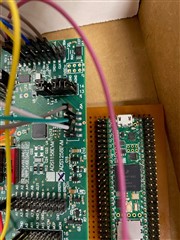
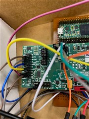
I am trying to read ads1258 using SPI with teensy 4.1 controller.

Below is teensy code

#include <SPI.h>

//#define IO_CHECK
#define SPI1_CHECK

const int spiCsPin = 38;//TO ADC J6.7
const int spiSckPin = 27;//TO ADC J6.3
const int spiMosiPin = 26;//TO ADC J6.11
const int spiMisoPin = 39;// TO ADC J6.13
const int DRDY=4; //ADC J6.15,output to
const int START=5;// TO ADC J3.3


byte stat,data1,data2,data3;
float dataF;

SPISettings spiMemSettings(1000000, MSBFIRST, SPI_MODE0);
void setup() {
Serial.begin(9600);
pinMode(DRDY,INPUT);
pinMode(START,OUTPUT);
pinMode(spiCsPin, OUTPUT); // SPI CS

// put your setup code here, to run once:
#ifdef IO_CHECK
pinMode(spiSckPin, OUTPUT); // SPI_SCK pin
pinMode(spiMosiPin, OUTPUT); // SPI_MOSI pin
#endif

#ifdef SPI1_CHECK
SPI1.begin();
SPI1.setMOSI(spiMosiPin);
SPI1.setMISO(spiMisoPin);
SPI1.setSCK(spiSckPin);
SPI1.setSCK(spiCsPin);
#endif

digitalWrite(spiCsPin,LOW);
digitalWrite(START,LOW);
delay(1000);
digitalWrite(START,HIGH);
delay(1000);

}

void loop (void)
{
if (digitalRead(DRDY)==LOW)
{
delayMicroseconds(30);
stat = SPI1.transfer(0x00);
data1 = SPI1.transfer(0x00);
data2 = SPI1.transfer(0x00);
data3 = SPI1.transfer(0x00);
if (data1>127)
{
dataF=(data1-128)*pow(2,16)+data2*pow(2,8)+data3-pow(2,23);
}
else
{
dataF=data1*pow(2,16)+data2*pow(2,8)+data3;
}

Serial.println(dataF, DEC);
}
}

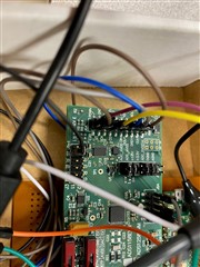
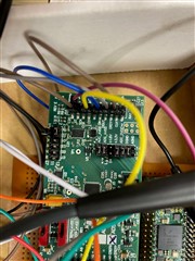
wave forms on the ads side as follows-:

spiSckPin = 27;//TO ADC J6.3(yellow)
spiMosiPin = 26;//TO ADC J6.11 (green)

The serial output is just zeros even though i input a sqaure pulse of 3.3 v to AIN0 wrt ground

kindly help

  • and I am using SP1 as default SPI is in use

  • Hi Samarth,

    Are you able to get any data out of the device? Can you try reading back your registers and reporting the results?

    Can you provide a schematic of the ADS1258 board? Note that in order to communicate between the two boards there must be a solid ground connection. This is often the issue with fly wiring multiple boards together.

    -Bryan

  • I am not sure how to read registers using SPI via teensy 4.1?

    Could You help to provide generic code?

  • Hi Samarth,

    There is example code on the ADS1258 product folder: https://www.ti.com/lit/zip/sbac222

    Note that since you are not using a TI microcontroller, there is limited code support we can offer. I will try to help you as much as possible, but it will be challenging to move forward if the SPI communication is not working properly on the MCU.

    -Bryan

  • Hi Bryan,

    I am using ADS1258 EVM.

    WIRING are as follows


    spiCsPin = 38;//TO ADC J6.7
    spiSckPin = 27;//TO ADC J6.3
    spiMosiPin = 26;//TO ADC J6.11
    spiMisoPin = 39;// TO ADC J6.13
    DRDY=4; //ADC J6.15,output to
    START=5;// TO ADC J3.3

  • Hi Bryan,

    the DRDY pin is always 1v even when I give square pulse of 3.3 v to input 1. is that normal?

  • Hi Samarth,

    Are you using just the ADS1258EVM or the ADS1258EVM-PDK (with the MMB0 motherboard)? Depending on your answer, how is the EVM / EVM-PDK being powered?

    How do you have the grounds connected between the two boards (the EVM and the Teensy board)?

    -Bryan

  • Hi Bryan,

    I got the board working and I am able to read the registers using the sample library. The issue was I did J4 connections wrog and my vcc and gnd were not correct.

    Now I had connected AIN0 to 3.3V but was not sure how to read a specific channel?

  • Hi Samarth,

    I would recommend reading the ADS1258 datasheet to answer these general questions. You will need to program the device in fixed channel mode, select only AIN0 to read from, and begin conversions. All of this is explained in detail in the datasheet. Moreover, there are a lot of existing ADS1258 questions and answers on E2E that can help you if you run into issues.

    Please give it a try on your own using the datasheet and the example code previously provided and let me know if you have any trouble along the way. If you get stuck, please let me know what you have tried and what is happening such that the intended operation is not working. Oscilloscope waveforms or logic analyzer plots will be useful if you run into problems.

    -Bryan

  • Hi Bryan,

    Thanks for your reply.

    Now I am able to get output from AIN0 channel as below

    left image yellow is input pulse, right hand is output serial plot from ADC.

    My doubt is when I change Switch S1 and S2 from center position to left most to set ref as VDD and VSS,

    adc reads constant 0V?!

    Do I have to change anything in code when we change reference?

    Code:

    #include <SPI.h>
    #include "ads12xx.h"


    const int Sck = 27;//TO ADC J6.3
    const int Mosi = 26;//TO ADC J6.11
    const int Miso = 39;// TO ADC J6.13
    const int START=5;// TO ADC J3.3
    const int CS = 38;//TO ADC J6.7
    const int DRDY=4; //ADC J6.15,output to


    //int RESET_PIN = 9;

    //Define which ADC to use in the ads12xx.h file

    ads12xx ADS;

    void setup()
    {
      Serial.begin(115200);
     
      Serial.println("Serial online");
      Serial.println("Serial online");
      ADS.begin(CS, START, DRDY);  //initialize ADS as object of the ads12xx class

      ADS.Reset();

      delay(10);

    }


    void loop() {
                test_AIN0();
    }
     

    void test_AIN0() {
      // struct conversion outputFromADC();
      uint8_t statusByte;
      int32_t regData;
      int32_t volt_val = 0;
      ADS.SetRegisterValue(CONFIG0, MUXMOD_FIXED | CLKENB_ENABLE);
      ADS.SetRegisterValue(CONFIG1, IDLMOD_SLEEP | DLY2_on | DLY1_on | DLY0_on | DRATE_0);
    //ADS.SetRegisterValue(MUXSCH, AINN0);
      ADS.SetRegisterValue(MUXSCH, AINP0|AINN1);
      //Data sheet ADS1258 P25 : 1 LSB=V_REF/780000h
      //0x780000=7864320 dec
      ADS.GetConversion1258(&statusByte, &regData);
      volt_val = regData;
      //Serial.print("Status byte = ");
      //Serial.println(statusByte);
      //Serial.println(volt_val, DEC);
      //Serial.println(volt_val, HEX);
      double voltage = (3.3 * volt_val / (7864320));
     // Serial.print("AIN0 voltage: ");
      Serial.print(voltage, DEC);
      Serial.println(" V");
    }

  • Hi Samarth,

    How are you powering the ADS1258EVM daughter card? How and where are AVDD and AVSS connected?

    You should not have to change any of the ADC register settings in order to use the different reference settings via S1 and S2. Can you confirm that this is the only thing you have changed? I.e., the system works fine with S1 = DAC and S2 = GND, then you switch to S1 = AVDD and S2 = AVSS and the system no longer outputs any voltage?

    -Bryan

  • Hi Bryan,

    I am powering ADS1258EVM daughter card via

    J5A- PIN 3 TO 3.3V from teensy

    PIN 5 TO GND

    PIN 9 TO 5V

    AVDD and AVSS i have done no connections.Assuming j4 jumpers config it?

    now I am not sure about my jumper config and which pin to connect for AVSS and AVDD.

    I also have doubts regarding J3 CONFIG.

    PFA MY J5A,J3 AND J6A connections

    J4 PIN READINGS

    ADC_AVDD=3.3V

    ADC_AVSS=0V

    1.8VPIN IS NOT CONNECTED VIA JUMPER

    3.3V PIN=3.3V

    ADC_DVDD=5V

    DGND=0

    AGND PIN IS NOT CONNECTED VIA JUMPER

    serial output error

  • Hi Samarth,

    It seems the AVDD and DVDD supplies are flipped. AVDD should be 5V with respect to AVSS (which is grounded in this case) and DVDD should be 3.3V.

    You should not need the jumper on AGND as long as you have the jumper on DGND, since AGND and DGND are tied together (J4-PIN12 and J4-PIN14).

    -Bryan

  • Hi Bryan,

    now my avdd is 5v and dvdd is 3.3v but output is constant 5v.

    can I ask if my cs and st config on J3 are correct?

    I am directly giving ST on j3 using a controller and removed its jumper, while I USE CS from J6A,keeping jumper on j3 still.

  • the code I am refering is from TI form on teensy and ads1258 as below

    #include <SPI.h>
    #include "ads12xx.h"


    const int Sck = 13;//TO ADC J6.3
    const int Mosi = 11;//TO ADC J6.11
    const int Miso = 12;// TO ADC J6.13
    const int START=5;// TO ADC J3.3
    const int CS = 36;//TO ADC J6.7
    const int DRDY=4; //ADC J6.15,output to


    //int RESET_PIN = 9;

    //Define which ADC to use in the ads12xx.h file

    ads12xx ADS;

    void setup()
    {
      Serial.begin(115200);
     
      Serial.println("Serial online");
      ADS.begin(CS, START, DRDY);  //initialize ADS as object of the ads12xx class

      ADS.Reset();

      delay(1);

    }


    void loop() {
                test_AIN0();
    }
     

    void test_AIN0() {
      // struct conversion outputFromADC();
      uint8_t statusByte;
      int32_t regData;
      int32_t volt_val = 0;
      ADS.SetRegisterValue(CONFIG0, MUXMOD_FIXED | CLKENB_ENABLE);
      ADS.SetRegisterValue(CONFIG1, IDLMOD_SLEEP | DLY2_on | DLY1_on | DLY0_on | DRATE_0);
    //ADS.SetRegisterValue(MUXSCH, AINN0);
      ADS.SetRegisterValue(MUXSCH, AINP0|AINN1);
      //Data sheet ADS1258 P25 : 1 LSB=V_REF/780000h
      //0x780000=7864320 dec
      ADS.GetConversion1258(&statusByte, &regData);
      volt_val = regData;
      //Serial.print("Status byte = ");
      //Serial.println(statusByte);
      //Serial.println(volt_val, DEC);
      //Serial.println(volt_val, HEX);
      double voltage = (3.3 * volt_val / (7864320));
     // Serial.print("AIN0 voltage: ");
      Serial.print(voltage, DEC);
      Serial.println(" V");
    }

  • Hi Samarth,

    Yes, the J3 jumper configuration should be okay. It would probably make more sense to either connect both flywires to J6 or J3, and not have one going to J3 and one to J6. But it should work

    Are you able to read any registers back from the ADC? In other words, are you getting any response from the device? It would be good to see a register read back on your scope

    -Bryan

  • Also, you had said that in your previous post you had gotten the ADC to work properly. What have you changed in the meantime such that you are not getting good data anymore?

    Now I am able to get output from AIN0 channel as below

    left image yellow is input pulse, right hand is output serial plot from ADC.

    -Bryan

  • Hi Bryan,

    My old issue got solved. I am able to precisely measure one channel now.

    The issue was I used wring port in code to measre.

    My current code as shown below

    #include <SPI.h>
    #include "ads12xx.h"
    //using default spi

    const int Sck = 13;//TO ADC J6.3
    const int Mosi = 11;//TO ADC J6.11
    const int Miso = 12;// TO ADC J6.13
    const int START=5;// TO ADC J3.3
    const int CS = 36;//TO ADC J6.7
    const int DRDY=4; //ADC J6.15,output to


    //int RESET_PIN = 9;

    //Define which ADC to use in the ads12xx.h file

    ads12xx ADS;

    void setup()
    {
    Serial.begin(115200);

    Serial.println("Serial online");
    ADS.begin(CS, START, DRDY); //initialize ADS as object of the ads12xx class

    ADS.Reset();

    delay(1);

    }

    void loop() {
    test_AIN0();
    }

    void test_AIN0() {
    // struct conversion outputFromADC();
    uint8_t statusByte;
    int32_t regData;
    int32_t volt_val = 0;
    ADS.SetRegisterValue(CONFIG0, MUXMOD_FIXED | CLKENB_ENABLE);
    ADS.SetRegisterValue(CONFIG1, IDLMOD_SLEEP | DLY2_on | DLY1_on | DLY0_on | DRATE_3);
    //ADS.SetRegisterValue(MUXSCH, AINN0);
    ADS.SetRegisterValue(MUXSCH, AINP1);
    // ADS.SetRegisterValue(MUXSCH, AINP0|AINN1);
    //Data sheet ADS1258 P25 : 1 LSB=V_REF/780000h
    //0x780000=7864320 dec
    ADS.GetConversion1258(&statusByte, &regData);
    volt_val = regData;
    //Serial.print("Status byte = ");
    //Serial.println(statusByte);
    //Serial.println(volt_val, DEC);
    //Serial.println(volt_val, HEX);
    double voltage = (3.3 * volt_val / (7864320));
    // Serial.print("AIN0 voltage: ");
    Serial.print(voltage, DEC);
    Serial.println(" V");
    }

  • Now I am trying to read multiple ports together.

    should I be using auto scan mode to simultaneously read all 16 Analog inputs?Could you suggest what changes to register I need to make for multi channel read?

    Thanks

  • DAC SINGLE CHANNEL RESULTS FOR REFERNCE

  • Now I am trying to read multiple ports together.

    should I be using auto scan mode to simultaneously read all 16 Analog inputs?Could you suggest what changes to register I need to make for multi channel read?

    BELOW IS MY CODE.I have connected AINCOM TO GND.

    RESULT:SERIAL OUTPUT SHOWS ZERO FOR ALL CHANNELS

    void test_continuousRead() {
      //  uint8_t statuses[8] = {};
      int32_t results[8]  = {};
      uint8_t statusByte;
      uint8_t channel;
      uint8_t valid;
      int32_t regData;
      ADS.SetRegisterValue(CONFIG0, MUXMOD_AUTO | CLKENB_ENABLE | STAT_ENABLE | CHOP_ENABLE | BYPAS_EXT); //CHOP_ON, external bypass on (for putting an external amplifier)
      ADS.SetRegisterValue(CONFIG1, IDLMOD_SLEEP | DLY2_on | DLY1_on | DLY0_on | DRATE_3);
      ADS.SetRegisterValue(MUXDIF, 0x00);
      ADS.SetRegisterValue(MUXSG0, 0xFF);
      ADS.SetRegisterValue(MUXSG1, 0xFF);
      //Data sheet ADS1258 P25 : 1 LSB=V_REF/780000h
      //0x780000=7864320 dec
      statusByte = 0;
      while (1) {
        for (uint8_t i = 0; i < 8 ; i++) {
          ADS.GetConversion1258(&statusByte, &regData);
          channel = (statusByte << 5);
          channel = (channel >> 5);
          results[channel] = regData;
        }
        Serial.print(millis());
        for (uint8_t k = 0; k < 8; k++) {
          Serial.print(" ");
          Serial.print((double)(5 * results[k] / (7864320)), 6);
        }
        Serial.println();
      }
    }

    Thanks

  • Hi Samarth,

    Can you help me understand what changes you made to fix your original problem? I did not fully understand what you did.

    To read from multiple channels: the ADS1258 has an Auto-Scan mode and a Fixed-Channel mode. This is selected via Bit 5 in the CONFIG0 register. Either of these modes can be used to read multiple channels. In Auto-Scan mode, you select a group of channels to read (e.g. Ch 1, Ch3, Ch4, Ch7, Ch15), and the ADC will sample & convert Ch1, then automatically switch and measure Ch3, then automatically switch and measure Ch4, and so on. When the ADC reaches the last channel, it loops back around and starts from the beginning of the loop again. You can also measure differential channels in this mode (e.g. Ch0 to Ch1, Ch2 to Ch3, etc.). Table 13 in the ADS1258 datasheet shows the different selections you can make. These selections are enabled via the MUXDIF, MUXSG0, and/or MUXSG1 registers.

    Fixed-channel mode only measures between the two inputs you select in the MUXSCH register. You select the channel connected to AINP via the MUXSCH[7:4] bits and the channel connected to AINN via the MUXSCH[3:0] bits. This is useful if you want to measure some other combination of channels that is not included in Table 13.

    In the end, it really depends on what channels you want to measure between with the ADS1258.

    -Bryan