- Ask a related questionWhat is a related question?A related question is a question created from another question. When the related question is created, it will be automatically linked to the original question.
This thread has been locked.
If you have a related question, please click the "Ask a related question" button in the top right corner. The newly created question will be automatically linked to this question.
Hi ,
Iam using DAC81404EVM with msp430-EXP432E401Y .Accessing the DAC using the GUI provided by BP-DAC81404EVM_1.0.0_installer_win.zip.
1)The DAC81404EVM with msp430-EXP432E401Y gets connected to PC.
2)DAC internal reference voltage is present.
3)SPI signals are reaching the DAC .
4)Configuration and bin files are programmed as per the doc below
1614.BP-DAC81404EVM_Debug_Procedure.docx
5)SPI configuration register setting are happening.
6) when i try to set DAC data register ,it resets to 0. kindly help in resolving the issue.
Regards
sundari
Hi ,
Welcome to E2E forum. i will help to solve your query.
1. You mentioned that you can able to access DAC8140 SPI register, did you able read device ID ?
2. Did you verified following supply VDD, AVDD, AVSS and IOVDD

3. Share your GUI screen shots(step by step)
1)unable to read device ID.
2)J17 1,4 5V
J17 2,3,5 gnd
3)when i try to set ,spiconfig ->0x0004 it takes and it doesn't reset .similarly for GENconfig and DACPWDWN.
4)DAC data registers resets to 0 whenever i try to set.
4)When we probe SPI lines, data are sent out from controller.
5) attaching the dac register setting.DAC81404.docx
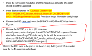
1. Did you replaced "OCFSPI.js "in file as per below step? this must be done.
2. Check IOVDD is going to DAC ? 3.3V
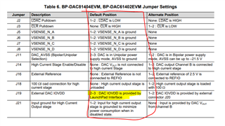
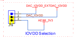
Your setup seems ok ..
Can you please share GUI screen snips how you are reading device id and oscilloscope snaps of SPI lines
i just press read register button by selecting the DEVICE -ID register.there is no spi transfer during read operation.
In GENCONFIG register if i set the RF_PWDWN_EN bit , current drops and if i disable ,current increases.readregister.docx
1. by default "immediate Write" option selected so write and write all register button are disable
- immediate write mean just entering value will write data directly and once you change option to "Deferred Write" other buttons are enabled.
Send oscilloscope capture all SPI signal(CS,SCLK, SDI and SDO)
2. Read Device ID and probe SPI signal
3. Write SPI configuration register and probe SPI signal
Want to confirm read /write happing in hardware.
above images are captured while writing to SPIconfig register with 0x0004.
Read operation is not happening .no spi signals observed.
During read operation , did you mean no CS, SCLK signal coming from hardware ?
If you getting CS,SCLK,SDO and not reflected in GUI then this is due file "OCFSPI.js " not replaced.
If write is happing but not read, It is not possible ..
Could you please upload firmware again and try .. please follow procedure as stated.
DAC voltage are changing after using same version of OCFSPI for of GCruntime8
i reprogrammed controller.but still unable to perform read.
1. ok, now issue is only register read from device correct ?
2. Are you sure that not getting any signal from SPI while reading ?
iam able to read and write into all register.
DAC values are getting updated and corresponding output comes DAC channel A,Band C.
Channel D output is always 5V for any input DAC input.
on power up any register write sequence is there before connecting PC to the controller?
Hi,
ensure DAC D is not in power down mode (by default all channels are power down state)
Address 0x03 => 0x0A84 ( device power up D[5]=0)
Address 0x09 => 0x0000 ( power up all 4 DACs)

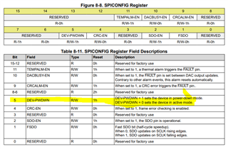
SPIconfig is set to 0x0004. Rest of the control registers are set to 0 .DAC register are load with required values. This is the register config i used.but still dAC channel 4 not working.
Hi ,
Jumper are in default position , j8(1,2) connected ?

VCC = ? , VSS ? , what voltage range selected ?
jumper j8 is present.but still o/p is at 5v.
what r the changes to be done to work in other voltage ranges like 0 t0 15 v?
Good,
Could you please share EVM setup picture and highlight supply rails so i can understand you connection are proper.

J17 1,4 5V
J17 2,3,5 gnd
To operate on 0 to 15 v then J17 pin4 was connected to 15V. DAC range register was set to 0 to 15V range. is that right ?
Hi,
Thanks for picture, seems all jumper are correct.
Yes, J17(4) connected to 15V for voltage range 0-15V.
In your, previous condition DAC channel 4 is working for 0-5 V ? still it always give 5V output irrespective of output set?
yes still DAC4 is not working.it always shows 5V (the voltage range wht we set)
Other issues are resolved.
Can you please change J17(4) to 10 V and check channel 4 behavior ? after changing it stick on 10V ?
Hi
1. Are you measuring DACD output at TP6 with reference to GND
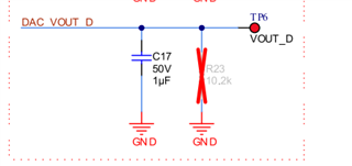
2. Power off the system and measure resistance using Multimeter across
TP6 with reference to J17(4) = ?
TP6 with refence to GND = ?
Hi,
I believe you are using the version A of the EVM in which we made intentional change to VSENSE_P and VSENSE_N connections to test some of the internal feature of the device.So DAC D will always be at AVDD supply.
if you need to have DAC D out on the EVM, please refer to the below thread in which we have explained the procedure to do the same.
Regards,
AK