This thread has been locked.
If you have a related question, please click the "Ask a related question" button in the top right corner. The newly created question will be automatically linked to this question.
Dear Sirs,
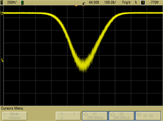
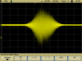
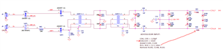
we use the ADS5560EVM with 1 MHz sinus analog input signal on the SMA connector J6 (single-ended). The signal generator has a 50 Ohm output. After connecting the input signal collapses in half, viewed with the oscillograph. Do you have any advice for us, please?
Thank you
Matthias
Hi Matthias,
The reason for the termination style on the EVM is explained in section 7.3.2.2 Example Driving Circuit. Which is the same circuit located on the EVM.
In order to take care of the sampling glitches, this type of termination style is preferred for best AC performance.
Removing the terminations can help gain the signal back up however, there might be some differences in AC performance, ie - lower SFDR.
We can help you modify the input frontend if can understand more about your application. Is your application a time domain application or frequency domain application?
Regards,
Rob
Dear Rob,
thank you. We want to analyze a modulated burst as seen in the following pictures. This is the raw analog burst signal. In essence we want to perform an FFT, but also need the raw signal to help with calibration and debugging.
As soon as we connect the signal to the ADS5560EVM, input J6, it collapses and it looks like only the modulated frequency of the burst remains. We have to scale from 200mV/div down to 20mV/div.
I look forward to your answer, thanks,
Matthias
HI Matthias,
Thanks for the additional information. This helps.
What is the frequency of the pulse? Between the extra termination on the frontend network and the transformers BW (0.250–750MHz) this might be the limitation here.
Also, do you need to DC couple the pulse into the ADC?
Please try this experiment, using your oscope, probe along the frontend network and see where the drop in signal strength occurs, this will help target the issue as well.
Next, see the pic below, I would make sure the following components are removed. And also replace C69/C68 as 0.1uF caps. If you look at the notes below, it seems they were changed to inductors.
Let me know if this helps.
Regards,
Rob
Dear Rob,
thanks for your hints. We don't need DC. Our frequency, approximately 550 kHz, is within bandwidth (0.250 - 750) MHz. It can be assumed that the input circuit (J6) reduces the amplitude. Now we use the programmable fine gain. On the other hand, a voltage follower at the input leads to decoupling. We carry out analysis in the frequency (FFT) and time domain.
Another question is this: Are the output data of the ADC available to us on the evaluation board? How can we adopt them for mathematical processing?
Regards,
Matthias
Hi Matthias,
Yes, the digital outputs from the EVM are exposed, but it would be easier to use the EVM in conjunction with the TSW1400EVM data capture board to capture the data & our HSDCPro SW. See the link. Then you can download the captured data and evaluate the data offline or on a separate program for mathematical processing.
https://www.ti.com/tool/TSW1400EVM
Regards,
Rob