This thread has been locked.

If you have a related question, please click the "Ask a related question" button in the top right corner. The newly created question will be automatically linked to this question.

ADS1605: Bad conversions

Part Number: ADS1605
Other Parts Discussed in Thread: THS4501, , THS4502, THS4541, THS4520, THS4503

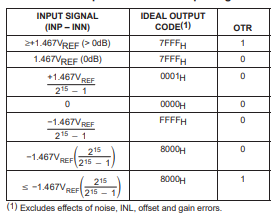
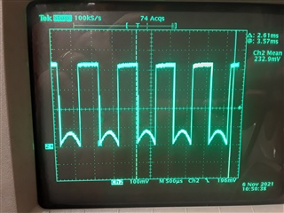
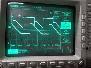
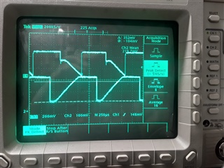
I am using the reference design recommendation in my circuit with the THS4501 driving the ADS1605. For any signal voltage below the Vmid level, the ADC output is correct. When the input Voltage exceeds the Vmid level, the ADC output becomes high for the 3 MSBs immediately, The lower bits seem to behave normally. I have the output going to a DAC and the waveform on the DAC is correct when the input is below the Vmid reference and at full scale when above it, which is what I would expect with the 3 MSBs being high. I cannot understand what can cause this behavior. Any help as to what to look for would be greatly appreciated.

Thank you,

Howard

  • Hi Howard,

    Can you share a schematic of your system and the input levels you are biasing to? What is the common-mode of your input signal? Have you measured the amplifier output directly? It sounds like you are saturating the THS4501. You may also try monitoring the ADC reference voltage to make sure it is within the supported range across your input range.

    Best,

    Zak

  • Zak:

    Thanks for replying. When monitoring the outputs of the THS4501 it is clear when the + signal goes above, and the - signal goes below the Vrefmid of 2.2V the ADC misbehaves as I described. When it is below Vrefmid on the + it operates properly. I am using the internal references on the part which I measured at 3.9V and 1.2V, which are not exactly symmetrical . I don't see a way here to upload a pdf to you for the schematic. I have checked this and the behavior is the same on multiple units. I built the  exact same circuit 20 years ago, and it worked fine then.

    Howard

  • Hi Howard,

    You should be able to add your file by clicking insert -> image/video/file and clicking the upload button in that menu. Alternatively I think you can actually drag and drop now.

    The reference voltage you've quoted is a bit low, but still well within spec. The VMID voltage should be much closer to 2.5V though so if you are seeing 2.2V, which is out of spec, then I suspect the VMID pin is overloaded.

    It's still not clear to me what the levels of your signal are so I think some plots of the FDA output in each case would be helpful. I believe you are effectively saying that positive differential voltages at the input pins are read fine while negative differential voltages saturate the output, or at least saturate the DAC. Can you confirm whether the OTR pin is high when you get bad readings? 

    If only the first 3 MSBs of the ADC output are high, this is actually within the range of the part. Remember the output of this is part is binary 2's complement with codes as shown:

    I would guess that your DAC is expecting an unsigned binary input and thus the negative codes from ADS1605 are out of range.

    Hope this helps!

    Best,

    Zak

  • DOPPLER4FPGA-11-SCHp1_6.pdf

    Zak:
    Drop and drag works. On pages 1 and 2 of the schematic you can see the parts we are discussing. Page 3 has the FPGA that handles the data. For now, for testing we are moving the data to the DAC on page 6 of the schematic. The LTC2654 DAC has the PORSEL pin tied high, so the DAC sees 0 as mid scale, the same as the ADC. Let me restate the problem, since from your questions, I don't think you understand my statement. If I inject a sine wave into the THS4501 AC coupled, then you get the image in the attached photo. For half the sine wave, you see a sine wave. For the other half, the output is always at full scale. Even if the DAC is not 2s complement, then you would still see the 2 haves of a sine wave, put the other half would be at the top of the picture going negative. I also injected a saw tooth waveform, and can clearly see that at the midscale transition, the output of the DAC goes high and stays high, all higher bits of the ADC output bits stay high also. The input is always within the ADC input range. Even when over driving the ADC the OTR pin is always low. To test that the DAC works properly, we created a counter in the FPGA and get the expected sawtooth output waveform, so we know that side is working properly. I also believe I am driving the ADC properly. I believe the ADC is not functioning properly, and other then having a lot of defective parts, I can't explain what I see. I am hoping that you can tell me what I am doing wrong. As I previously said, I built the same circuit 20 years ago, but only used 2 ADCs instead of 4 and it worked fine.

  • Hey Howard,

    Thank you for providing the schematic and scope plot, this helps to put things in context. Just to make sure I understand, can you also confirm where in the schematic this plot is captured from? Is this the VOUTA pin of the DAC before amplification? It looks like the scope is set to 100mV/div so your output is quite small and centered around 232mV, whereas I would have expected it to be closer 2.5V. Unless of course you're just using a 10:1 probe and the scope isn't factoring that in Slight smile.

    It would also be helpful if you could take a scope capture of the THS4501 output directly so we know for sure whether or not the signal is clipped at all before it enters the ADC. Some older op amps and ADC modulators would have a tendency to introduce a phase inversion if their input is overloaded. I'm honestly not certain if either of these parts exhibit that behavior so it would be helpful to confirm. The fact that the ADC isn't reporting an overvoltage doesn't necessarily mean you aren't still saturating. Some modulators have to be driven a good bit past their maximum operating point before this error flags.

    While I agree that if the DAC can't process 2's complement we should see the other half of the sine wave at the top, I still suspect there is a format mismatch. I would only expect this kind of behavior to happen if you have a phase inversion from saturating an analog component, or a difference in digital formats. From the LTC2654 datasheet as far as I can tell the PORSEL pin only changes the voltage the DAC powers up to, it does not impact the DAC transfer function. Based on the way they define the transfer function I don't believe the DAC can interpret 2's complement and any "negative" values from the ADC will force the DAC to the other rail. As to why we don't see the other half of the sine wave, your schematic calls out the 12-bit version of the DAC. I realize you would probably use the same symbol for both, but are you actually using the 12-bit or the 16-bit version? If it is the 12-bit then I would guess that for the swing you are looking at if your FPGA isn't decimating the ADC value before sending to the DAC then the DAC is actually fully driven into the rail for the range of signal you are testing. Perhaps if you tested with a large amplitude signal you would start to see the other half of the sine wave?

    In any case, it definitely seems like it is necessary to do a format conversion between these two parts so I think that would be a good first step towards resolving this issue.

    Best,

    Zak

  • Zak:
    I will ask my FPGA guy to convert back from 2s complement. However, I can't see how that will help. The conversion to 2s complement is to invert and add 1, so we would subtract 1 and invert. If we didn't do that the output would just be inverted and off by 1 count. There would be a wrap around only for the most positive output level.

    We are using the DAC with 12 bits, and the data is aligned appropriately. I have attached a picture I took at the + output of the THS4501 when I had a sawtooth input. (ignore the glitch at the beginning, my probe moved). I am over-driving the input. The scope probe as you observed is a 10x probe that doesn't register on the scope. The first picture has the DAC output on the upper trace, and the THS4501+ output on the lower trace. The second photo is the same except that the lower trace is the THF4501- pin on the lower trace. Now that I think about it, it doesn't look like the voltage goes as low as it should on both outputs. I double checked the references, and have 3.9 V, .9 V and at pin2 of the THS4501 the mid point, 2.37 V

    Howard

    Howard

  • Hi Howard,

    From this at least we can tell a few things:

    1) The FDA outputs don't appear to be well balanced. The + input looks to be swinging around 2.5V, but the - input looks to be swinging around 1.7V. If this sawtooth exercises the full scale range of the part and these plots were taken under the same conditions, both of these waveforms should be centered at 2.5V. If you're AC coupled, 800mV is quite a large DC offset to have between the outputs and it isn't split evenly between the outputs. One problem I see is that you have a 10 Ohm resistor on the supply line of the THS4501. This part has a fairly high quiescent current and pretty limited swing to the rail and this resistor is only going to make that worse and introduce additional distortion with AC signals. Given that the THS4501 even at full swing cant drive the full signal range of the ADS1605, I would advise against the power supply filter, though I don't think that's the only problem.

    2)  The shift might be due in part to the tolerance of the resistors you are using around the FDA. Remember CMRR is going to degrade with any mismatch and even 0.1% resistors could produce a worst case CMRR of 54dB. The output capacitors are also going to contribute significantly to this and in general if you are going to use common-mode output capacitors you should size them at least 15-20x smaller than the differential capacitor you use so that differences in the cutoff frequencies does not convert what should be common-mode noise into differential. 

    Since the FDA is in a single-ended configuration, that means the common-mode is actually going to move around a good bit as shown in this plot where the green curve is the voltage at VGM/VGP and the red curve is INP

    2) Furthermore, the 10 Ohm resistor will reduce the supply voltage by up to 300mV. The specs are a little weird but the 25C output swing with 5V shows +/-3V swing. With that resistor that is effectively +/-2.7V. Since the ADS1605 has a range of +/-1.467Vref and you measured Vref at 3.0V, that's +/-4.4V. That means you're only actually utilizing ~60% of the ADCs range, which is fine if you're ultimately converting to 12 bit resolution but it does mean you're effectively throwing away the MSB. Note this also means you'll never be able to saturate the ADC so you'll never see the OTR pin go high. But given that the ADC output is in 2's complement, which starts at FFFF (-1) when VIN+ < VIN- and ends at 8000 (-32768), that would mean the DAC will saturate at the positive rail as soon as the ADC code goes negative until it gets to -32 (once the 12th LSB changes) and then start ramping down from there. That's only around a 5mV loss though too so I wonder if the ADC actually has an issue with where the input common-mode is at?

    Best,

    Zak

  • You raise some interesting points, but I don't think it completely explains the ADC behavior. I will dig into the THS4501 operation a little more, there does seem to be something not quite right there. Maybe the + and - outputs not tracking properly can confuse the ADC? Anyway, it will take me a few days to investigate this further and get back to you. However, I don't understand your comment about the capacitor values. The reason is that the values are lifted from your datasheet, see figures 10 and 11. All 3 capacitors in those recommended driver circuits are the same 100 pF that I am using, I copied the circuit. If fact, I am fairly sure that the entire circuit was given to me by a TI applications engineer  when I first designed this in 2000.

    Thanks,
    Howard

  • Hey Howard,

    This part is a little odd in that all of the specs are given at 2.0V common-mode, which you'll notice isn't actually large enough to accommodate the ADCs full input swing. The common-mode spec is given as 2.0V typical, and all of our typical plots only show the common-mode swept out to 2.4V. If you're using the VMID at 2.5V to set the common-mode, it's possible that your inputs are swinging a little too far or the ADC requires a tighter common-mode range. On one of your plots for example the amplifier swung to ~4.9V, while we give the absolute input voltage as a maximum of 4.7V. Even if you're not saturating the ADC differentially, this may cause abnormal behavior.

    After looking at it again, with the values chosen and based on where the cutoff frequency is, you can probably get away with the 100pF caps without degrading CMRR too much in the passband. To demonstrate my point though here is your filter driven with a common-mode source. If all components are perfectly matched then you would expect to see no change in the differential output as the input changes over frequency. In reality though these components are obviously not going to be perfectly identical and that skew between the two filters means that you will actually see a small differential voltage due to changes in the common-mode. Here is a Monte-Carlo sim of CMR assuming you use 1% resistors and 10% caps:


    At the full bandwidth of 2.45MHz (assuming you run at max sample rate) the CMR is likely to fall between -40 to -60 dB. Over most of the input frequency range it will actually be much better since the cutoff frequency of this filter is rather high. This definitely isn't the main source of your problem, but just something I wanted to point as a general best design practice. If you're running at 5MHz for example you'd actually be fairly sensitive to common-mode noise at multiples of the sample rate since this will alias back into the passband. If you reduce the common-mode caps the CMR will improve. Here's the same example but with the other caps changed to 10pF:

    Overall the CMR is about 20dB better across frequency, which makes sense because I reduced the caps by a factor of 10.

    Best,

    Zak

  • Zak:

    Thanks, maybe the datasheet needs updating. We definitely will not run above 4 MHz. typically 1 MHz. I was just following the recommendation. I am going to see if I can dig up the old prototypes of what we built 20 years ago to see why those boards worked. We never put them into production because we couldn't get the processor to run fast enough back then.

    Howard

  • Hi Zak:

    I proved that the problem is post the ADC, although it is not resolved yet. However, when I respin the board, it seems I should switch to theTHS4502 rather then the THS4501 I now have. Also, can I connect the mid reference directly to the THS4502 or do I still need to keep the buffer I have now? If you have any other suggestions as well, it would be appreciated. Thank you for all your help so far.

    Howard

  • Hey Howard,

    Sorry for the long delay, I was out of office all of last week. Glad you have been able to identify the problem! You could use the THS4502 or THS4503 as a drop in as long as you know the die temperature won't exceed 60C as per the warning in the datasheet. Otherwise if you are re-spinning the board anyways you might consider switching to a device like the THS4541 or THS4520 in QFN or VQFN packages. If the amplifier is running from the same supply as the ADC, then you could decide to float the VOCM pin as the amplifiers will automatically default to mid-supply as the VOCM reference. Either way, if you're going to use the VMID pin of the ADS1605 to bias anything I would still recommend keeping the buffer. Most of the FDAs have VOCM input impedance <50kOhms and since the VMID is used by the internal conversion circuitry you want to avoid disturbing it. Also keep in mind though that the ADS1605 does best with an input common-mode of 2.0V, so you might actually want to bias this with a divider into your buffer instead of using VMID, assuming the head room is not an issue for you.

    Best,

    Zak

  • Zak:

    Thanks for all your insight. I closed the issue for now.

    Howard