


Hello all,
We face a problem understanding the behavior of the ADS1605 ADC to the C6748 when connected to the UPP port. We connected the ADC to the UPP as described below.
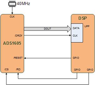
We setup the UPP port to use DMA which is clocked using the /DRDY line from the ADC and a DMA count equal to 1024. So, on every falling edge of the /DRDY line we capture a new sample until we reach the DMA count. After we received the requested number of samples we prepare a new acquisition. During this preparation period we are not interested in any samples but we want to configure the UPP for the next acquisition. In other words we would like to configure and start the next acquisition but we do not want to receive any clock signal, see figure 2.

However this /DRDY does not behave the way we expect. What we expect was that the /DRDY is stopped during the period where the /RD is high since the data on DOUT of the ADC is in tri-state (high impedance). But what we see is that /DRDY continues to produce clock a signal. Is this correct behavior?
We have two workarounds for this issue but we first want to be sure that we did not overlooked something:
Workaround 1 (Use the /RESET line instead of /RD):
The problem with this solution is that we have to acquire 47 samples extra which is required for the ADC to produce accurate data. We can throw away these extra samples. However this solution does not feel like a good solution to me.
Workaround 2 (Use an AND port to force the clock low during the preparation period)
This solution seems to be the best solution if there is no other solution.
Questions summarized:
- Why does the /RD line continues to produce clock while DOUT is in tri-state?
- What about our workarounds?
- Is there a better solution?
Thanks for any help.
Kind regards,
Frank Litjens
