This thread has been locked.

If you have a related question, please click the "Ask a related question" button in the top right corner. The newly created question will be automatically linked to this question.

ADS1261: ADS1261

Part Number: ADS1261

Hello Bryan,

we are using ADS1261 in a magnetic Sensor Product. Few months back I had reached you in this forum for the same, you clarified my doubts on ADS1261. 

Now, we had a prototype hardware with magnetic sensor connected to ADS1261. As we know, ADS1261 output 24 bit counts. We extracted most significant 16 bits from the 24 bit count for the calculations. we observed the 16 bit counts are coming with variation of +/- 20 counts in a zero magnetic field. This is a very huge variation. Ideally this variation should be +/- 1 counts as per the sensor output. This huge variation in counts is due to some noise, it could be induced at ADC input as well, not very sure. 

ADC configuration used is: 1200SPS, SINC1, PGA BYPASS, CHOP MODE OFF, 50us start conversion delay, external 2.5 V reference (AIN0, AIN1) , Pulse (One shot) conversion, Self Offset & Gain calibration

Now below are my questions:

1) Is there a way to filter/reduce the Noise by doing ADC configuration (probably for 1200 SPS) ?  Does SINC filter configuration and Chop mode can help here? Please let me know.

2) As per ADS1261 datasheet, separate Analog and Digital grounds should be connected to ADS1261. But, in our design we connected digital ground for both. Does this contribute any noise which results in high variation of counts? please let me know.

Thanks,

Ram.

  • Hi Ram,

    From the ADS1261 datasheet, the maximum noise-free resolution you can expect from the device is 19.2 bits at 1200 SPS, sinc1, gain =1. This assumes the full-scale range of the ADC is used and VREF = 5V. If VREF = 2.5V then you are already losing 1x bit of resolution, so the maximum noise-free resolution has been reduced to 18.2 bits. Then, if your input signal is +/-2.5V, the noise-free resolution will be reduced further. What is the output signal you are trying to measure from the sensor?

    If you look at Table 1, you can see that the ADS1261 noise tends to decrease as the data rate decreases and/or the sinc filter order increases. In other words, use a slower data rate or sinc2/3/4 filter to get better noise performance. However, if the noise is coming from somewhere else in your system, reducing the ADC noise will likely not help.

    Chop mode is meant to reduce offset (see section 9.4.2), but chop mode also has the added benefit of averaging two results together. This reduces the noise by √2, at the expense of longer latency.

    Also, the ADS1261 datasheet specifically says to use a single ground plane. There are options in case this is not feasible, but a single solid ground plane for both analog and digital is always recommended

    -Bryan

  • Hi Bryan,

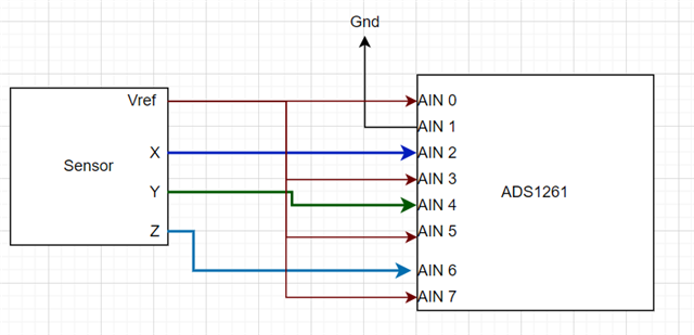
    Above picture shows the connections between Sensor and ADS1261. the output of each X, Y and Z axis can go for (0V - 4V) respectively. these are connected to AIN2, AIN4 and AIN6 respectively. Now Vref is 2.5v coming from sensor and it is connected to AIN0, AIN3, AIN5 and AIN7. AIN1 is connected to ground.

    Now I selected AIN0, AIN1 as external reference.

                             AIN2, AIN3 for X axis measurement

                             AIN4, AIN5 for Y axis measurement

                             AIN6, AIN7 for Z axis measurement.

    This is the ADC input channel configuration. so my output signal from sensor is 0V to 4V and it is selected as positive MUX input, 2.5V is selected as negative MUX Input. can you please tell me what is the noise-free resolution for this configuration? I need at least 16 bits of noise free resolution for my application. I selected 1200SPS, SINC1 configuration because in this configuration I will get all X, Y and Z channel counts in less than 4.5ms time, which is required for my design. But I am seeing the counts variation as +/- 20. 

  • Hi Ram,

    Assuming no other noise in your system, you could expect at best around 17.5 noise-free bits using 4V of a 5V FSR at 1200 SPS, ainc1, gain = 1.

    Therefore, it is likely that there is noise being introduced by other components, possibly the sensor, power supplies, etc. If the sensor generates a magnetic field that could be causing issues. If there is any noise coming from the sensor VREF, that will directly impact the measurement.

    In other words, there are lots of places that noise can enter your system. I would encourage you to try to step through each component and see you can find the source (or sources) of noise and then remedy them. For example, try a low noise VREF instead of the sensor VREF to see if that improves performance. Or, try a precision source so you can rule out any potential signal chain issues.

    You can also try replicating the datasheet noise test to make sure you can get datasheet noise performance: "The noise data
    are acquired with inputs shorted to mid-supply, based on consecutive ADC readings for a period of ten seconds or 8192 data points, whichever occurs first." This will at least confirm that the ADC portion of your system is operating correctly

    -Bryan

  • Hi Bryan,

    Many thanks, for the detailed explanation. we measured the sensor VREF and it is a clean signal. As you suggested there is a need to check other components of the system. 

    1) I checked noise test description in datasheet and is not clear to me. Can you please tell me how to do the noise test? Like what input should we give,              reference, what to check in the counts etc... Just you can brief me.

    2) I tried to calculate the noise free resolution by the formula given in datasheet. for example, 1200sps, sinc1, 2.5v reference. Here, the uVrms and uVp-p are      2.3 and 17.

        now, noise free resolution = ln((2*2.5*10^6)/17)/ln(2)

                                                  = 18.16

       18.16 I am getting, Is this correct for 4v output signal?

    3) We have analog circuits like magnetic sensors in our design. Should we be having separate ground for Analog and Digital circuits? Since digital ground is         noisy and it contaminates analog signals.

    Thanks,

    Ram.

  • HI Ram,

    I would recommend reviewing the "ADC Noise" content in our Precision Labs training material: https://training.ti.com/ti-precision-labs-adcs

    The information in this collateral will help you better understand how noise is measured and how it is calculated for your system.

    Typically you want a solid, common ground plane for both analog and digital. This FAQ helps explain why in more detail: https://e2e.ti.com/support/data-converters-group/data-converters/f/data-converters-forum/755516/faq-pcb-layout-guidelines-and-grounding-recommendations-for-high-resolution-adcs

    You should also consider how close the sensors will be to the measurement system. If they will be far away then it is unlikely that there will be too much EMI, as I would assume the field strength for these sensors is pretty low (unlike a motor for example).

    -Bryan