This thread has been locked.

If you have a related question, please click the "Ask a related question" button in the top right corner. The newly created question will be automatically linked to this question.

ADC16DX370EVM: ADC16DX370EVM implementation with ZC706/KCU105

Part Number: ADC16DX370EVM
Other Parts Discussed in Thread: LMK04828, TSW14J57EVM

hello 

I have received the ADC (ADC16DX370EVM)  put I have a few question regarding its combatiablity with KCU105/ZC706.

 I started working on the evolution board with ZC706 but I am facing a problem of detecting the FPGA board in the HSDC program, 

I directly connected the ADC16DX370EVM FMC to the ZC607 FMCHPC then I used the default configuration in the ADC16DX370EVM program.

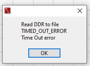
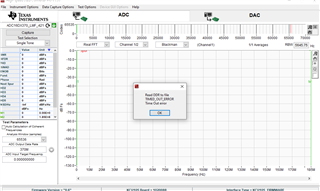
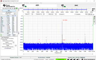
Finally I opened the HSDC program unfortunately  the FPGA board was not detected. 

Based on your answer for my question in https://e2e.ti.com/support/rf-microwave-group/rf-microwave/f/rf-microwave-forum/1050121/lm97937evm-general-questions-on-lm97937evm/3907562?tisearch=e2e-sitesearch&keymatch=%20user%3A501387#3907562

the board should be compatible with KCU105/ZC607 without the need for a TSW14J10EVM data convertor. 

best regards 

Ahmed

  • Hi Ahmed,

    we will have to check. The HSDC PRO most likely need TSW14J10 EVM as a bridge to connect to KCU105. I do not recall KCU102 can connect directly to HSDC PRO. 

  • Ahmed,

    HSDC Pro does not support this ADC when using the TSW14J10EVM with either a KCU105/ZC706. I would suggest applying for free TI JESD204B IP that would work with these boards. Go to the following link to request this IP that also comes with example reference designs and documentation. 

    https://www.ti.com/tool/TI-JESD204-IP

    Regards,

    Jim

  • Hello Jim,

    I am really confused, when I bought the ADC I though it would be combatable with the HSDC Pro and KCU105 based on your answer in  https://e2e.ti.com/support/rf-microwave-group/rf-microwave/f/rf-microwave-forum/1050121/lm97937evm-general-questions-on-lm97937evm/3907562?tisearch=e2e-sitesearch&keymatch=%20user%3A501387#3907562.

    Does using JESD204B IP will allow me to use the EVM with the KCU105 without the need of converter/different fpga board ?

    and Will I be apple to receive, save  and view the sampled data just like HSDC pro software ?

    Regards

    Ahmed

  • Ahmed,

    The TSW14J10EVM could possibly work but would require some modification and testing to existing files. This will take time and manpower which is currently limited right now. That setup was used on several TI JESD boards but not all. If you would like to pursue this route, I can send some files that might help you get started on this. Support will be limited though.

    You can use the TI IP without any other boards assuming all of the required signals are mapped on the ADC FMC connector, which I think they are. The TI IP and provided software will use the ILA analyzer to capture the data in Vivado. The captured data then can be imported into the HSDC Pro GUI for viewing. See attached file describing this. This is a much better approach than using the TSW14J10EVM and the Vivado project that comes with it as it is not optimized for end user cases. 

    Regards,

    Jim

    ADS42JB69 KCU105 TI204c-Setup.docx

  • Jim,

    My intention is to just use the ADC16DX370EVM and KCU105 board I was never thinking about using any of the TSWxx EVM boards,  All I am looking for is the capturing the sampled data from  ADC16DX370EVM through KCU105 FPGA board. I read some of the previous community posts where some used KCU105+ADC16DX370EVM without any problems from example post 1

    One of the things I tried is following the HSDC pro with KCU105 user guide, unfortunately I didn't have a local network for both the host-PC and kcu105 board there is mismatch in the IP address (Board IP address: 192.168.1.10, Host IP address in HSDC: 10.81.6.164) therefore I can not detect the FPGA. 

    As for the ADC files we have (ADC16DX370EVM.ini) or I can download .ini file given in post 1.

    I also applied for the Free JESD204B IP and waiting for a response.   

    Regards, 

    Ahmed

  • Ahmed,

    I have never used this EVM and I am trying to find someone who has. I was able to download the files you mentioned and they are attached. I am waiting to hear back from the engineer that created these. Please feel free to give this a try while waiting for my reply.

    Regards,

    Jim

    5672.ADC16DX370 (LMF_421) using the KCU105.pptx6378.ADC16DX370_LMF_421.ini8814.KCU105 HSDC Pro User's Guide.pdf 

  • Jim,

    Thank you for the replay I was following KCU105 HSDC Pro User's Guide.pdf, is there a way to make a common IP address between the host computer and KCU105 board without the need for switch or router.

    Regards,

    Ahmed

  • Jim,

    I got a reply concerning the JESD204B IP CORE I am just so confused about the specific mode of operation or the JESD link parameters. I need to know how does it effect my design and my board I wish could get some help.

    best regards,

    Ahmed

  • Hi Ahmed,

    You may refer to the training site below for more information about JESD204

    https://www.ti.com/applications/industrial/jesd204-technology.html

    It is a system dependent setup (depends on your application), and it is best that you become familiar with it to make decisions for your system. Thank you.

  • thank you hang, I will take a look at it.

    meanwhile I have been trying to follow the HSDC Pro with Xilinx KCU105, these are the steps I followed:

    1. I connected the ADC16DX370EVM directly to KCU105 Board (FMC HPC).
    2. Programed the KCU105 using the firmware located in : “C:\Program Files (x86)\Texas
      Instruments\High Speed Data Converter Pro\KCU105 Details\Firmware\KCU105_TI_DHCP.bit".
    3. I adjusted FMC VADJ to 1.8V.
    4. Connected KCU105 and ADC16DX370EVM though Ethernet port using the IP address of the board I Found in UART port.
    5. Turned on the  ADC16DX370EVM power.
    6. I Configured the ADC16DX370EVM GUI
      1. after hardware required hardware modifications to use LMK04828 as clock source (Remove R72, R73, R78, and R79 and place 0-Ω resistors on R74, R75, R80, and R81)
      2. pressed Configuration 2.
      3. then changed the JESD204B lanes to L=2 based on our (ADC16DX370_LMF_421.ini) provided by you. 
      4. then pressed Calibrate ADC.
      5. In the JESD204B tab the ADC/JESD20B status shows all lights are ON except  SYSTEM Re-Align is OFF.
    7. The input signal to is provided to VINA, it is set to 100MHz sin wave.
    8. I opened the High Speed Data Converter Pro program then connected the to kcu105 without any problems.
    9. Set the sampling frequency to 370MSPS in the program.
    10. Choose the ADC16DX370_LMF_421.ini in select ADC option and I pressed capture and I got this error.

    Any suggestions?

    thank you in advance.

    best regards 

    Ahmed

  • Ahmed,

    What is the status of all LED's on both boards in this situation?

    Regards,

    Jim

  • Jim,

    the KCU105 GPIO LEDS status after configuration:

    0:OFF

    1:ON

    2:OFF

    3:Blinking

    4:Blinking fast

    5:Blinking fast

    6:Blinking fast

    7:ON

    the KCU105 GPIO LEDS status after pressing capture button:

    0:OFF

    1:ON

    2:ON

    3:Blinking

    4:Blinking fast

    5:Blinking fast

    6:Blinking fast

    7:ON

    the ADC16DX370EVM LEDS status before pressing configuration button in GUI:

    OVRA/TRIGRDY : ON

    OVRB/TRIGGER : ON

    AFTER PRESSING THE CONFIGRATION BUTTON THE STATUS STAYS LIKE THIS:

    OVRA/TRIGRDY : OFF

    OVRB/TRIGGER : OFF

    THIS IS THE STATUS PF THE READ REGISTER:

    best regards,

    Ahmed

  • Ahmed,

    Please try this test using external clock mode as described in the documents I sent. Once you get everything working, then I would attempt on-board clocking.

    Regards,

    Jim 

  • Jim, 

    I can not obtain an extra signal generator for the external clock I am very limited right now. can you give me suggestions for this current situation ?

    regards,

    Ahmed

  • Jim, 

    I managed to follow the pdf u sent and tested with an external sampling clock, and everything worked fine. I show the status of the leds with capturing:

    KCU105 LEDS:

    0:ON

    1:ON

    2:ON

    3:Blinking

    4:Blinking fast 

    5:Blinking fast

    6:Blinking fast

    7:ON

    ADC16DX370EVM LEDS 100:

    OVRA/TRIGRDY : OFF

    OVRB/TRIGGER : OFF

    SYNC = ON

    There is no problem. 

    Now how can I work with the internal clock.

    regards,

    Ahmed 

  • Ahmed,

    I think the FPGA reference clock was set wrong. Go ahead and modify your board for internal clock, select configuration 2 in the Clock DIST tab, then go to the low level tab and set the LMK register 0x120 to 0x10 as shown in the attached slide.

    Regards,

    Jim

    FPGA_CLK_divide_16.pptx

  • Jim, 

    I managed to make the internal clock work on the board. I used an input single tone sin wave of 1.57542 GHz cause its the range I am planning to work .

    I am expecting the intermediate frequency to be in 95MHz (intermediate frequency  = 95MHz when I used the external sampling clock), when I used the internal clock at 370MSPS as in configuration 2, the intermediate frequency fell in 82.4 MHz .

    I tried the same input signal with a different internal sampling clock (295MSPS) by changing the DCLKout2_DIV to 10, DCLKout8 = 20, DCLKout10 = 20, SYSREF_DIV= 320.  the intermediate frequency fell in 82.4 MHz  which does not make no sense ?

    I have a few questions concerning the capturing and saving to a file (.bin).

    can I save the sampled data continuously into binary file (.bin) or save big amount of data (I want at least 1s of sampled data and it can go up to 60s of data) ? and if so how can I do that ? 

    best regards,

    Ahmed.


  • Ahmed,

    To use the board with internal clock mode, you will need to install either Y1, Y2 or Y3. Have you done this? If so, what is the frequency of this part? 

    If one of these is installed, you probably have a wrong setting for the LMK. Please measure the FMC_FPGA_DEVCLK (185MHz) and LMK_ADC_DEVCLK (370MHz) to make sure these are at the correct frequency.  

    Regards,

    Jim

  • Jim, 

    I did not read that part of the device, I though the LMK04828 can provide everything, I got one question how can I find an appropriate crystal oscillator module that can work with the card and what is its criteria ?

    and if I used an external reference clock what is the expected value that I should use ?

    I am waiting for a reply concerning  this question "can I save the sampled data continuously into binary file (.bin) or save big amount of data (I want at least 1s of sampled data and it can go up to 60s of data) ? and if so how can I do that ?"

    best regards, 

    Ahmed

  • Ahmed,

    Look at the LMK04828 data sheet regarding help with picking a frequency. If you do not use the LMK internal PLL's, you would have to provide an oscillator that is equal to or a 2x times your desired frequency.

    The current firmware uses FPGA internal memory to store data. This is limited to 32,768 samples. The firmware would have to use external memory on the board to do larger captures which is not supported. You would have to create your firmware if you would like to do this.

    Regards,

    Jim

  • Jim,

    I got a few questions about the EXTREF because i am little bit confused :

    1. What is the benefit of the EXTREF if the LMK04828 can provide clocks the ADC device with a sampling clock and SYSREF clock using the internal oscillators VCO0/VCO1 ?
    2. what are the required modifications if I am going to use a signal generator as an input in the EXTREF port ?
    3. Does your jesd204b IP Core provide any costume way to save continuous data ? capture then save ?

    regards,

     Ahmed

  • Jim, 

    is there any update on my question ?

    I found this on the HSDC application, I can do a continuous capture for the sampled data and it should save the data to a file "write captured data to file"  put it does not seem to work ? and I don't understand why ?

    best regards,

    Ahmed

  • Ahmed,

    The software/firmware that was created to be used wit the KCU105 was limited and this feature was not supported. You would need to use the TSW14J56EVM or TSW14J57EVM to use this feature. 

    Regards,

    Jim