Other Parts Discussed in Thread: ADS1115
Reading over the datasheet for the ADS101x and it appears that when reading the conversion register, the least four significant bits (0:3) should always read back 0h. However, I'm seeing values all over the board when sampling. Examples:
- MSB: FF (1111 1111)
LSB: F6 (1111 0110) - MSB: 00 (0000 0000)
LSB: 04 (0000 0100) - MSB: FF (1111 1111)
LSB: AF (1010 1111)
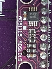
I'm attempting to read from an SCT current transformer biased to +2.5v (supply to ADS1015 is +5v) and wired to A0/A1 (multiplexed). Communicating via I2C. The Config Register is written 0x84 0xA3 which I believe should translate to:
- Start a single conversion (when in power-down state)
- AINp = AIN0 and AIN1
- FSR = +-2.048v
- Continuous-conversion mode
- Data Rate: 2400 SPS
- Traditional comparator
- Comparator Polarity: Active low
- Nonlatching comparator
- Disable comparator
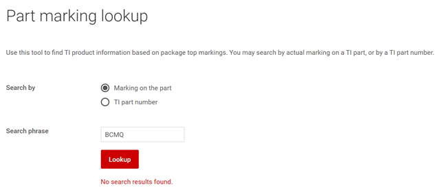
Can someone confirm that the values should actually read 0h in those four least significant bits? I've tried a couple of dev boards and have the same issue, but they are from the same manufacturer - I'm almost wondering if they have wired the board improperly (wouldn't be the first time - had a batch of BMP280 dev boards come with the BMP280 rotated 180 the wrong direction) but I feel like given I can at least communicate with the board over I2C it's wired somewhat correctly enough.