This thread has been locked.

If you have a related question, please click the "Ask a related question" button in the top right corner. The newly created question will be automatically linked to this question.

DAC8775: STM32F446RE show no communication with DAC8775

Part Number: DAC8775


Hi gents

I am facing with an output of DAC8775 card, getting 0.0mA on any channel. 
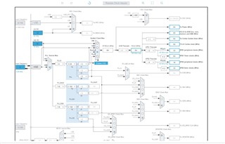
DAC8775 Schematic

DAC775_Schematics.pdf

Clock Configuration

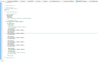
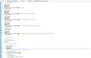
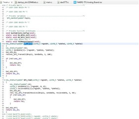
Main.c (for getting 20mA out in Channel A)
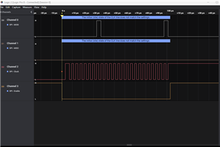
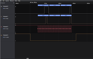
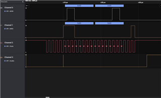
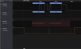
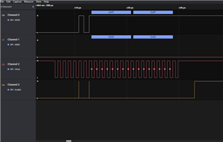
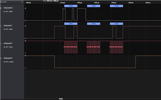
Settings:

1. Clock Polarity(CPOL): High

2. Clock Phase(CPHA): 1 Edge

3. Prescaler: 32

4. NSS signal type: Software

5. CRC calculation: disabled
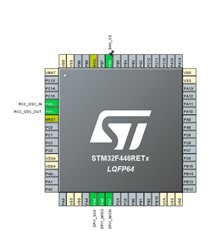
PinConfig

Kindly Advise anyone where i am wrong..

  • Mohammed,

    I always recommend looking at the SPI communication with an oscilloscope or a logic analyzer. It's important to see the digital communication between the microcontroller and the device. For this device, I'd look at the SCLK, SDIN, SDO, and /SYNC lines just to see that the communication is exactly what you think it is. Once you can grab a shot of that, post it back to this thread.

    Another useful test would be to write to and read back from one of the registers. You could just read from the status register, which should give you a 1000h readback, but I'd also try writing to and reading back from the DAC data register from one of the DACs. Use something other than all 1s or all 0s, you want to make sure you're reading real data.

    I didn't see anything wrong with your sequence when I took a quick look at it. This is how I would generally set the sequence:

    Reset
    Enable buck-boost
    Configure buck-boost (or just use default)
    Enable reference
    Configure DAC (range and maybe code)
    Enabel DAC output

    If you can, I would consider getting the DAC8775EVM. It has the device and is controlled though USB using a SM-USB-DIG controller. The software GUI is easy to use and you can look at the digital lines going in and out of the device to verify operation against your board and code.

    Regardless, start with looking at the SPI communications going between your microcontroller and device on the board. Post back with what you see.

    Joseph Wu

  • Hi Joseph,

    Thanks for your suggestion. Today I get the new logic analyzer for SPI analysis. After capturing data it seems all is ok, but there is an error during the reset of the microntroller. 

    Error: The Initial state of the clock line dose does not match the setting (It always comes after reset)

    Attached Screenshot of the trend from the logic analyzer.

    Please advise what's wrong in this..

  • Mohammad,


    Looking at your plots, I don't see anything in particular that is incorrect. I think this is the sequence that you're sending:

    010001h DAC reset
    060001h Select Buck-boost Converter A selected
    070001h Config buck-boost positive enabled, negative disabled
    030030h Select DAC 0030 Enable SDO, Channel A selected
    04D01Ch Config DAC D01C Current limit 24mA, HART disabled, output enabled, Slew rate enabled, 4-20mA range
    05FFFFh Set DAC data register

    Additionally, it looks like the SPI is set up so that the data is clocked in on the falling edge of SCLK. Generally, I use the SPI with the SCLK idling low, but that's not a strict requirement based on the timing diagram in Figure 1 of the datasheet. Also, the SPI clock is rather slow, running at about 250kHz, but that shouldn't be a problem either.

    I would definitely check the physical connections and make sure the SPI signals are reaching the device. I would also alter your sequence a little bit. Once you enable the SDO with the write to 03h, I would try to read back from the device. Right now, there's no movement on the SDO line, and it would be best to first ensure that there's any communication getting to the device. If your SCLK does not reach the device, it would also cause nothing to happen on SDO. Again make sure that the SDO is enabled after the write to 03h.


    Joseph Wu

  • Hi Joseph,

    Thanks for your response.

    Yesterday I forget to tell you with above code DAC was responding with  0.32mA & 9.99 Vdc at channel A.

    As per request I have capture SDO pin data, I kept the prevous code same just added read function as below

    Logic Analyzer Trend (Complete trend for Code-withoud repeating)

    Below are the screenshot for each spike after reset.

    At 0xFFFF (05h), DAC channel A out- 0.32mA, 9.99 Vdc

    At 0x0FFF (05h), DAC Channel A out, 0.03mA, 1.01 Vdc. (This is not included in this logic analyzer data)

    Don't know why Voltage is changing although we set it to 4-20mA out.

    Don't know why current is so low..

    Please advise..

  • Mohammad,


    I'm sorry, I didn't understand what you were having problems with. I had thought that you were having problems with communication, and that you weren't getting a response from the device. However, it looks like the output is changing with the communication from the device, although the responses are incorrect.

    One thing to ensure is that the reference is enabled and that you can measure it on the board. Without the reference, the DAC output will be incorrect, and that might be what you are seeing. If you are using an external reference, verify that the reference voltage is correct and that the internal reference is not enabled.

    I often use the EVM to test out the device operation, and I generally start up the device with the following:

    - Start with a reset using the RESET pin
    - Enable the buck-boost
    - Start the reference
    - Set the power-off condition to Hi-Z for both IOUT and VOUT
    - Set the DAC mode
    - Enable the output
    - Set the DAC code

    That generally sets up the device for operation, and I can start using the device.


    Joseph Wu

  • Thanks

    Joseph,

    There was a mistake on my side in not enabling internal reference voltage.

    I set 02h to 0x0013, it starts working....

    Thanks once again..

  • Mohammad,

    I'm glad you got your system working. 

    One thing that I did want to mention is that if you are using the slew rate mode to set values, I would use the pin reset (instead of the reset command) at the beginning of operation. We've noted some issues where there were problems in using slew rate mode without a start with the pin reset, where the output may not track.

    If you have more questions, feel free to post back.

    Joseph Wu