Other Parts Discussed in Thread: AFE5832,
Hi Sir/Madam,
when we use AFE5832LP device to develop portable ultrasound for medical application, we came across a problem as follows and do not know how to solve this. Since this is the 1st time using AFE5832,could you help us to solve this problem. Thank you very much!
Best regards,
Kevin Niu
//Register 0X01
//BIT 14 LVDS_RATE_2X 0 = 1X rate 1 = 2X rate
//BIT 5 DIS_LVDS 0 = LVDS interface is enabled 1 = LVDS interface is disabled
//BIT 14 GLOBAL_PDN 0 = The ADC die operates in normal mode 1 = The ADC die enters complete power-down mode
AFE5832_CFG(0x01, 0x0000);
//Register 0X03
//BIT 15-13 SER_DATA_RATE 011 = 10X
//BIT 12 DIG_GAIN_EN 1 = Digital gain enabled
//Bit 4 1,must
//0111 0000 0001 0000
AFE5832_CFG(0x03, 0x7010);
//Register 0X04
//BIT 8 PAT_SELECT_IND 0 = All LVDS output data lines have the same pattern
//BIT 4 MSB_FIRST 1 = The MSB is transmitted first on serialized output data
//Bit 3 DATA_FORMAT 0 = Twos complement format for output data
//Bit 1-0 ADC_RES 11 = 10-bit resolution
//0000 0000 0001 0011
AFE5832_CFG(0x04, 0x0013);
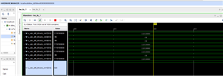
In DESKEW mode, the register 0x02 = 0x2100, in fpga system, the data 0101010101 captured by ILA capture is right.
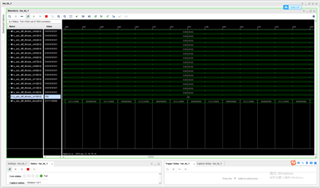
In sync mode, the register 0x02 = 0x2080, in fpga system, the data 1111100000 captured by ILA capture is right.
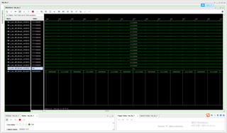
In All 1s mode, the register 0x02 = 0x2200, in fpga system, the data 1111111111 captured by ILA capture is right.
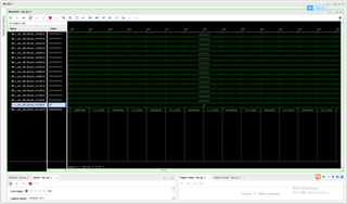
In RAMP mode, the register 0x02 = 0x2380, in fpga system, the data captured by ILA capture is error.
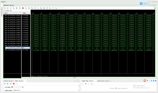
In RAMP mode, the register 0x02 = 0x23C0, in fpga system, the data captured by ILA capture is error too.
