This thread has been locked.

If you have a related question, please click the "Ask a related question" button in the top right corner. The newly created question will be automatically linked to this question.

ADS1291: ADS1291 ECG Data range

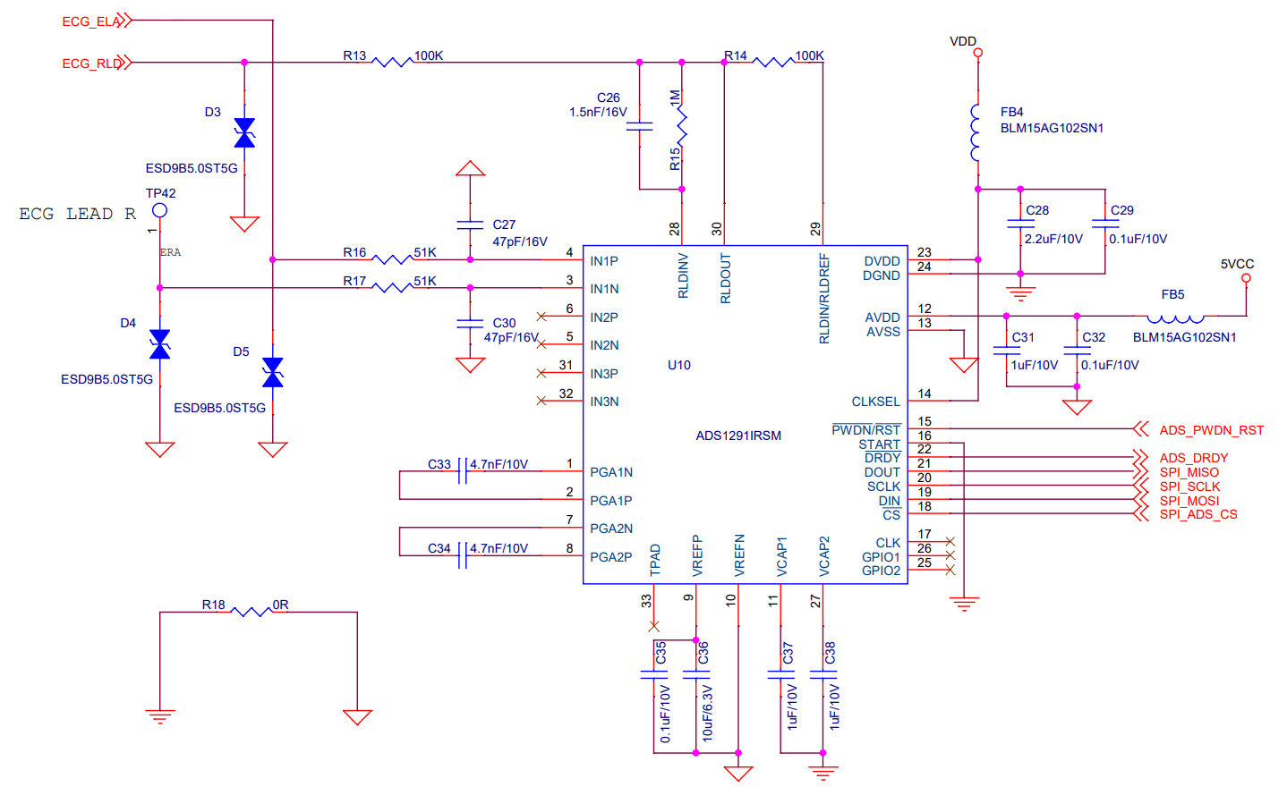
Part Number: ADS1291

Hi.

I'm working on ECG measurements with ADS1291.

The range of values keeps changing when ECG is measured on the wrist with ADS1291, can you tell me why?

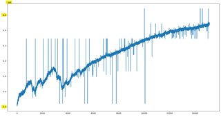
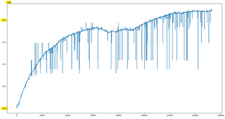
If you look at the pictures above, you can see that the range of data values is different even though we measured it twice with the same setting.

Also, the ECG values are in units of 5.
(ex. Also, ECG values are in units of 5.)

Is there a reason for this?

Thank you.

  • Hi Kim,

       May I ask what was the source of the ECG signal?

       How long was it measured/recorded?

        Is it from a ECG simulator or a human body(if it's from human subject, was the subject talking, moving, breathing quickly or deep breathing during the measurement)?

       Did you use any RLD or BIAS output?

       Do you have any DC blocking(i.e. patient protection) capacitor in your design?

       Have you tried to inject any low frequency(<= 2 Hz) and low amplitude(<=4mV) sinusoid wave to take a look?

       You may also take a look of this Thread -

    https://e2e.ti.com/support/data-converters-group/data-converters/f/data-converters-forum/687111/ads1291-ads1291-ecg-signal-is-abnormal

      it may also due to the electrodes, electrodes patches, gel, human impedance.

    Thanks,

  • Hi.

    Thank you for replying.

    I measured it on the human wrist for 30 seconds.

    During the measurement, I didn't speak or move, I just did the measurement for 30 seconds

    Below is the value I set.

    Thank you.

  • Hi,

    Do you have/use a evaluation kit/board(EVM)?

    Do you also have a ECG simulator?

  • Hi.

    Thank you for replying.

    I didn't use a simulator.

    Thanks

  • Do you have/use a ADS1291 evaluation kit/board(EVM)?

  • Hi

    Thank you for relying.

    We don't use ADS1291 evaluation kit/board

  • Hi,

    I am checking your register configurations.

    In the meantime, 

    Can you inject any low frequency(<= 2 Hz) and low amplitude(<=4mV) sinusoid wave to take a look?

    I suggest get an ECG simulator to do the test if this is for product development.

    Can you use ECG simulator to do the test in that way, we may know whether the drift come from the human body, environment or the circuits?

    I suggest get an ADS1291 evaluation kit/board(EVM) to do the same experiment if this is for product development.

    Did you use any RLDOUT or BIAS output?

    Do you have any DC blocking(i.e. patient protection) capacitor in your design?

    Which Clock Frequency do you use fCLK=? Did you set the CLK_DIV register accordingly?

    CONFIG2 is set to ‭1110_0000(E0) - this means

    1. using Lead-Off Comparators‬(PDB_LOFF_COMP); you may turn PDB_LOFF_COMP off if not using or to simplify the test conditions.

    2. using internal reference 2.42V; Could you probe the voltage at VREFP and VREFN and see if there is any noise?

    3. disable oscillator clock output; ok.

    LOFF is set to ‭1111_0000‬(F0) this means

    1. set some threshold for the lead off comparators and select 6nA DC lead off detection method. ok

    CH1SET is set to ‭0110_0000‬(60) this means 

    1. Use Channel 1 for normal electrodes(not routing any RLDIN to channel inputs) and PGA gain is set to 12. Gain might be too high, suggest to alter gain from 1 to 6 or 8 and observe the signal and noise or SNR?

    CH2SET is set to ‭1000_0001‬(81) this means 

    1. ‬Power down Channel 2, Gain set to 6(default) and inputs shorted.  Ok.

    RLD_SENS is set to ‭0010_0000‬(20) this means

    1. Enable the RLD buffer. Are you using RLD electrode? if not, you may power down PDB_RLD
    2. disable RLD lead-off sense. ok.
    3. disconnect all input channels' outputs(RLDxP, RLDxN) to RLD buffer. ok.

    ‭LOFF_SENS is set to 0000_0011‬(03) this means

    1. default the current source direction. Ok.
    2. disable lead off detection for Channel 2. Ok.
    3. Enable lead off detection for Channel 1. Suggest to turn off if not using and doing tests/experiments to isolate issues.

    LOFF_STAT is set to all 0s this means

    1. set the CLK_DIV to 0 indicate the fCLK is 512 kHz. Please confirm.
    2. bit[4:0] are read only, so make sure there is no error when writing.

    I see you are using ADS1291 that has no R(respiration feature), please confirm.

    ‭RESP1 is set to 0001_1110‬(1E) means 

    1. disable respiration demodulation and modulation circuitry. ok.

    RESP2 is set to 0000_ 0111‬(07) means 

    1. For ADS1291 without Respiration feature, set RESP_FREQ to 1. ok
    2. RLDREF_INT default to use internal voltage reference for RLD. ok You may turn RLD_AMP On and Off and observe if there is any signal difference.

    DC or DC drift could always be there due to body, skin conditions, electrodes, patches, environment and other factors/sources if there is no filter.

    People may try and test the following -

    1. insert a DC blocking cap(try and test 0.1nF to 0.5uF) in series before the input.
    2. put a 0.05 Hz active Hight Pass Filter before the input.
    3. post processing to remove DC and drifting by DSP.

    By doing/implementing above, people are making the front end become AC-coupled, which has some trade-off and Pros and Cons when compare with DC coupled(i.e. may have some drifting), so people will need to do experiments/tests/analyze(results, performances, resources, etc) to decide which method is appropriate for their applications.

    Thanks

  • Hi,

    This ticket/thread has been pending for more than 1 week.

    For house cleaning, I am closing this ticket/thread.
    If you may have other question, feel free to open another ticket/thread.

    Thanks