This thread has been locked.

If you have a related question, please click the "Ask a related question" button in the top right corner. The newly created question will be automatically linked to this question.

ADS5294: SNR for higher input analog frequency ?

Part Number: ADS5294

Hi

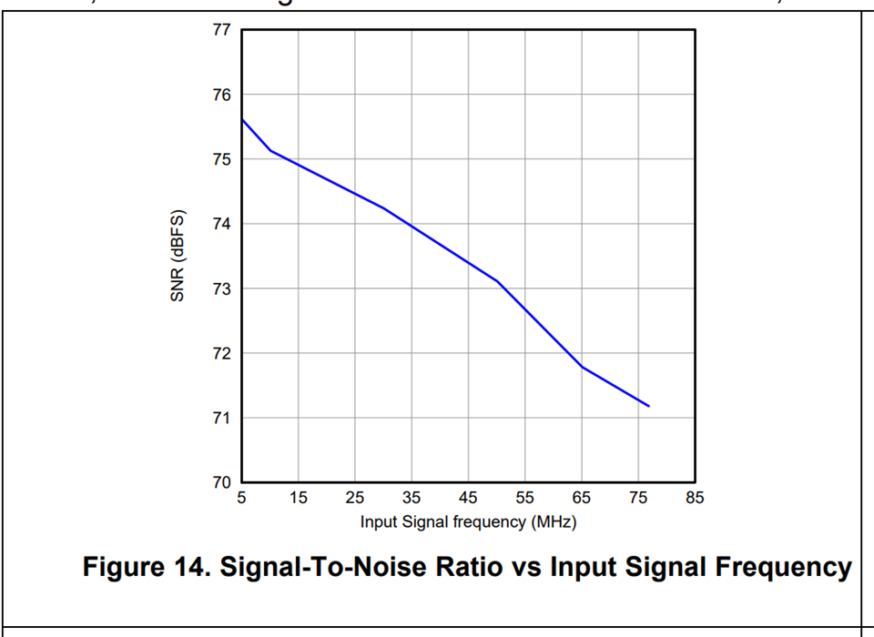
I wanted to know what will be the SNR for a input analog frequency of 160Mhz to180Mhz for ADS5294 with adc clock of 74Mhz.

Regards ,

Ashish

  • Hi Ashish,

    Thanks for writing to us.

    Based on your specifications, your signal lies in the 3rd nyquist band. 

    You would see a SNR degradation as compared to 1st nyquist band because of the mismatch between the bandwidth of internal ADC stages.

    I don't have data for 74 Msps but in the datasheet, we have shared the SNR data with input frequency at 80 Msps sampling rate. I think the ballpark number should remain close to this.

    From Figure 14 in the datasheet, we can extrapolate the expected SNR for 160 MHz to 180 MHz which comes around 66.2 dBFS to 64.9 dBFS respectively.  


    Thanks & regards,

    Abhishek

  • Hi Abhishek 

    Thanks for replying.

    I have another doubt that in data sheet, as shown in the pic , having a input analog frequency of 160Mhz it reduces the max amplitude to 1Vpp , so does this affect the SNR ?

    Thanks & regards,

    Ashish

  • Hi Ashish,

    For frequency higher than 80 MHz, the amplitude of the input signal has to be reduced proportionately to keep the Gain-Bandwidth product (A.w) constant to maintain the SNR performance. 

    But due to the bandwidth mismatch SNR degradation is expected according to the Figure 14. 

    So, the input amplitude reduction itself takes care of the SNR degradation by keeping the slope of the curve in the figure 14 almost constant. No further degradation is expected.

    I hope it answers your question. By the way, does this performance acceptable to you?

    Thanks & regards,

    Abhishek

  • Hi Abhishek,

    I trying to check the performance of ADS5494 in my board design , I have attached the Schematic and HSDC pro output below.

    8637.adc_1.pdf

    Im giving a ADC clock of 74Mhz and 160Mhz analog input frequency from a vector signal generator which passed through bandpass filter. 

    Im able to get SNR of 49dBFs only , so what can be done to improve the snr and also can you be able to simulate this frequency in evaluation board and  share the results.

    Thanks & regards,

    Ashish

  • Hi Ashish,

    Thanks for sharing your results and schematics.

    Please allow me some time think on it and get back with some recommendations.

    We can check the performance in the lab. Unfortunately, this week I have some tests already planned. I can do this test next week in the lab on the EVM.

    Thanks & regards,

    Abhishek

  • Hi Ashish,

    I gave some thought about the waveforms you shared.

    I suspect that your SNR is not being limited by the noise floor but it is being limited by the spurs/harmonics that are seen in the FFT. I have highlighted the same in the waveform below.

    So to understand it better, can you please tell me the SNR after removing these harmonics in the SNR calculation. You can use the option Notch frequency bins in the Test options and remove around 30 or so harmonics. Figure below shows the way to do it in HSDC Pro. The datasheet numbers are usually provided with these harmonics removed.

    Next thing I wanted to understand from you is about your application. What is the application for this system? Are you looking for better noise performance i.e. SNR or better strength ratio of the fundamental signal to the strongest spurious signal in the output  i.e. SFDR.?

    Please let me know your inputs.

    Thanks & regards,

    Abhishek

  • Hi Abhishek

    We wanted to use this adc for radar application and frequency of radar is 160mhz to 180mhz. Ideally we want both SNR and SFDR to be better  , but here we want better SNR  compared to SFDR.

    Also I will try the settings changes and let you know.

    Thanks & regards,

    Ashish

  • Hi Ashish,

    Thanks for sharing the details of the application.

    Please share your observations after removing the harmonics. I will plan to setup the ADS5294 EVM in the lab this week and will help you further to resolve the issue.

    Regards,

    Abhishek

  • Hi Abhishek

    I have uploaded the HSDC pro output above ,after removing 30 harmonics .

    Thanks & regards,

    Ashish

  • Hi Ashish,

    Thanks for sharing the observation. 

    After rejecting these harmonics, there is still some amount of degradation. I suspect that this is due to the trimming of bandwidth mismatch in the device.

    Typically we trim the bandwidth mismatch for operation within 80 MHz range.

    Please allow me some time to do experiments on the EVM and figure out the how to get expected SNR. I will set up the EVM and shall let you know my observations as well.

    Will get back to you within this week.

    Thanks & regards,
    Abhishek  

  • Hi Abhishek ,

    Were you able to simulate the inputs in your EVM ? if yes , Please share the output details .

    Thanks & regards,

    Ashish

  • Hi Ashish,

    I am working from home from last 2 days due to COVID related issue at my end.

    I am hoping to get negative result by Monday. So once I'm in lab. I'll capture the data and share my observation.

    I am also talking internally with the designer on this one, am waiting for his inputs as well.

    Thanks & regards,

    Abhishek


  • Hi Abhishek ,

    Hope you are in good health.

    I am just waiting for you output details of EVM .

    Thanks & regards,

    Ashish

  • Hi Ashish,

    Abhishek is currently out of office due to personal emergency. Just to update you, he was able to replicate the issue on his end in the lab and has reached out to the designer for additional clarification. We will provide an update by end of this week.

  • Hi Praveen,

    Were you able to get the output report of EVM simulations ?

    Thanks & regards,

    Ashish

  • Hi Ashish, 

    We sincerely apologize for the delay. Unfortunately, Abhishek is still on leave and we are a bit stretched at the moment in resolving all the issues. We will positively respond to this query by next Thursday. 

    Thanks,

    Karthik

  • Hi Ashish,

    I am sorry I was out of office for quite a while due to personal emergency.

    I came back to office and took the device performance data for the input frequency above 80 Msps.

    I found consistent results as the extrapolated waveform.

    Below is the data for 170 MHz input at 80 MHz sampling rate.

    The SNR observed is close to 65 dBFS. I have proportionately reduced the input amplitude as well.

    The reason I think it is not working in your case might be because you are not putting a band pass filter in the signal path and lot of reflections and sampling glitches are coming due to unbuffered ADC. 

    Could you please check the performance by introducing a BP filter of 170M and share the result. 

    The device user guide also specifies the same as shown below.

    Also, note that the signal source I have used for this experiment is SRS SG382 and it have very good phase noise performance. It could also be possible that your performance is being limited by the signal source you are presenting to the ADC.

    Thanks & regards,

    Abhishek

  • Hi Abhishek

    Good to hear from you , I hope you are well.

    I try using bandpass filter still i got around SNR= 55.8dbfs


    Im feeding 170mhz from a vector signal generator (SMBV100A) and adc clock source from AFG31000 . My application requires 74Mhz ADC clock so I doing testing in this clock frequency.

    I seen the datasheet for both instrument the phase noise is good.

    Im doubting my adc schematic because you mentioned that " sampling glitches are coming due to unbuffered ADC" ,could you elaborate more on this , should i do changes in my schematic ?

    Thanks & Regards

    Ashish

  • Hi Ashish,

    It's strange that your noise floor is higher than what I am seeing after putting the BP filter. I think the filter is not functioning properly, can you share the details of the band pass filter you are using. 

    By the way, if possible can you share your contact details on my email : abhishek.vishwa27@ti.com. We can connect over phone and try to resolve this a little faster. If your office is in India, we can plan to send our band pass filter to you and you can check if that is the case.

    By sampling glitches, what I meant is that the input to the ADC is coming from the source directly and there is not buffer in the path. Typically for unbuffered ADCs sampling glitches may come and could reflect and deteriorate signal characteristics. This phenomenon is usually avoided by the use on narrow Band Pass filter in the signal chain.

    I compared your schematic with the EVM and seems like it is the same. So, I dont think you need to do any changes in the schematic.

    Thanks & regards,
    Abhishek