This thread has been locked.
If you have a related question, please click the "Ask a related question" button in the top right corner. The newly created question will be automatically linked to this question.
Hi,
An application question for the DAC7562 12-bit version.
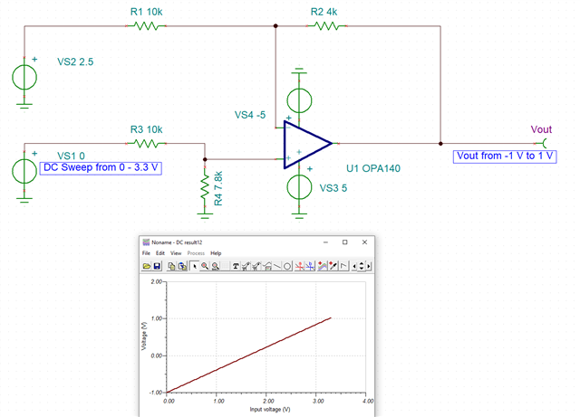
Any suggestions for the datasheet bipolar output circuit (page 44) to work with +/-5V supplies and output -/+1V? The DAC is at 3.3V supply so I would figure the output voltage goes 0-3.3V (or pretty close to it). This is to drive the Vg pin of the LMH6503 VGA. I am using the OPA140 opamp.
thanks for any help.
Hi Dennis,
I used TINA-TI to simulate your question and the circuit I found was:
I tried to make the circuit line up with the bipolar circuit on page 44 that you mentioned. If R1 and R3 are my standard R values, then R2 (top) is R/2.5 and R4 (bottom) is R/1.282.
Thank you,
Lucas
Hi Lucas,
Thank you very much for this. I think this has answered my main question.
From your tina schematic, with the opamp running at a gain a bit above 1 is there any chance for any instabilities here?
(usual gain here should be 1+ R2/R1, or 1+4/10 = or 1.4)
I was trying to make this app note work for me here but was not really getting anywhere:
dennis brown
Hi Lucas,
Another follow up question. In that linked app note from my last message there is a compensation capacitor used across the output to the inverting input. The app note lists a value of 150pF and it seems good. Does raising this value any higher have bad effects? I can get rid of the output peakiness by increasing this capacitor to 470pF but I am not certain of the downsides to doing so.
Hi Dennis,
The OPA140's datasheet has several noise measurements and performance graphs, including some at a gain of 1.
https://www.ti.com/lit/ds/symlink/opa2140.pdf?ts=1657653202261 (page 16)
Increasing the compensation capacitor will also directly decrease the gain bandwidth product.
Thank you,
Lucas
**edit: changed global BW product to gain BW product
Thanks Lucas.
Can you keep this thread open one more day? I may have another question to ask tomorrow and that would be it.
Hi Lucas,
I think my questions are answered with respect to any instabilities. I don't usually use TINA simulator as I find it to be tedious and it did not fail me this time. In any case using ltspice I was able to see instabilities in the opamp design if there is no Ccomp across the output to INV input. If you load the output of the opamp with 0.01uF capacitor you can generate an oscillation. If you add a Ccomp of 25pF or more this oscillation goes away. Going to 150pF does not seem to be problematic. I don't know if I will put in a 0.01uF load cap but it will be a placeholder on my board for further testing.
With a 1pF Ccomp, I see this:
With Ccomp of 150pF I see this:
I do want to thank you again for the application circuit.
dennis brown