This thread has been locked.

If you have a related question, please click the "Ask a related question" button in the top right corner. The newly created question will be automatically linked to this question.

AMC1106M05: Data timing related to modulator clock

Part Number: AMC1106M05
Other Parts Discussed in Thread: TMS320F28388D,

Hello,

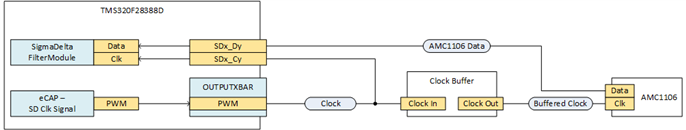
I am struggling with the signal timing of the AMC1106M05 delta sigma modulator, together with the TMS320F28388D. In principle what I have is this:

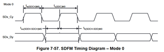
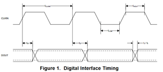
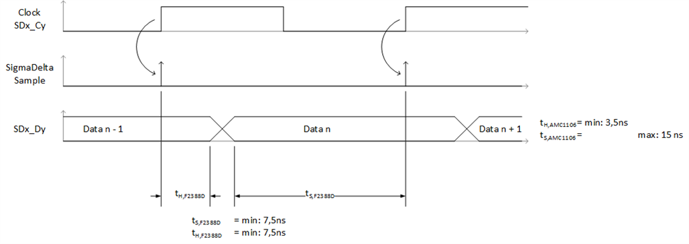
The timing diagramm will look like this:

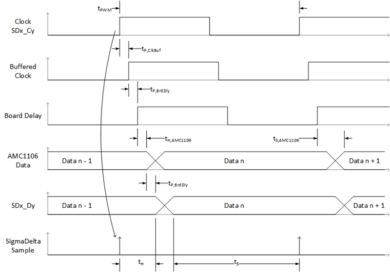
For evaluating that requirement for the hold time is fullfilled, I take the following values from the datasheets of AMC1106 and TMS320F28388D:
tH,AMC1105 = 3.5ns (Hold time of data output after rising edge of clock input)
tS,TMS320 = 1*PLLRAW + 5ns = 10ns (Required hold time, SDx_Dy wait after SDx_Cy goes high)

The hold time of the signal chain is calculated by the following formula:
ttP,ClkBuf + tP,BrdDly + tH,AMC1105 > tS,TMS320

If I assume that clock buffer is quite fast (hard to find a slow clock buffer), or maybe even not in the signal chain, then the delay is tP,ClkBuf = 0ns ... 1ns. Further the delay caused by the PCB signal transmission is in the range of tP,BrdDly = 1ns ... 3ns. The formula will result in:
t= 0ns + 1ns+ 3,5ns = 4,5ns, and this is unfortunatley lower than 10ns.

In other words this would mean, that at the moment the TMS320F28388D is sampling the data, it is not assured that the AMC1106 is holding the data output stable long enough.

Is my implementation correct? Do I have a mistake in thinking somewhere?

Best regards,
Michael Kettler

  • Michael,

    When F28388D, if the PLLRAWCLK = 400 MHz, then both setup time and hold time requirement is 7.5 ns.The definition of td (delay time) and th (hold time) is different from setup and hold time definitions in F28388D. td (delay time) mentioned in AMC1106 is the hold time mentioned in F28388d.So, according to AMC1106 datasheet, you have 15ns which is well over 7.5ns required. In case of setup time, it can be calculated in (50 ns - 15ns = 35ns). You should have ample setup and hold time required.

    F28388D

    AMC1106

    Regards,

    Manoj

  • Hello Manoj,

    thank you for the quick answer. Unfortunately I cannot agree.

    The 15ns you mentioned is the delay time of AMC1106. This is the maximum time AMC1106 needs, to have updated data on its data output. But the principle in the sampling should be different in my point of view. When F2388D is getting the rising edge at the clock input, it will sample the previous data, not the updated one. Therefore the AMC1106 has to gurantee a minimum hold time of the "old" data. And this minimum time is 3.5ns and is too less to fullfill the requirements.

    I tried to simplify my timing diagram, and checked again the datasheet of F2388D:

    ts,F2388D: Setup time, SDx_Dy valid before SDx_Cy goes high
    th,F2388D: Hold time, SDx_Dy wait after SDx_Cy goes high

    So the hold time is the requirement that causes problems.

    In the timing diagram you see, that F2388D is sampling data, when there is the rising edge at its clock input. At this time there is still the "old" data value present at its data input. The data has to be held stable for a minimum time of 7.5ns. But you see that AMC1106 has only a minimum hold time of 3,5ns after it received an rising clock edge. So there is a very pessemistic gap of 4,0 ns.

    Nevertheless it is a good point that PLL clock could be increased. This will relax the timing requirements of F2388D a little bit. But still I see no solution.

    Regards,
    Michael

  • Michael,

    I'm looping an expert from modulator team. Please give a 1 (or) 2 business days for him to respond.

    Regards,

    Manoj

  • Hi Michael and Manoj,

    The AMC1106 changes its output with the rising MCLK edge.  So, yes - the minimum hold time is 3.5ns and MAX delay until the new bit is valid is 15ns.  That gives you 11.5ns of uncertainty between old data and new data.  One solution ((Manoj, you may recall this) was to invert the clock that is seen by the modulator, so that the SDFM and AMC are 180 degrees out of phase.  That would give you the 15ns MAX delay 0f the AMC starting from the falling edge of the SDx_Cy giving ~10ns setup and 25ns hold time.  Our motor control systems team has also implemented a second PWM timer that can provide a predictive delay to ensure proper data capture.

  • Hello Tom,

    okay. So at least I know that I did not have a mistake in thinking.

    I will check if it is possible to insert a inverting buffer into the signal chain.

    Another possibility is of course the phase shifted PWM you mentioned. On the first view this should be possible by using one of the ePWM units. This has of course the disadvantage that I would have to spend a "real" PWM unit for the modulator clock. At the moment I planned to use a capture compare unit in PWM mode.

    So thank you for your time.

    Regards,

    Michael