This thread has been locked.

If you have a related question, please click the "Ask a related question" button in the top right corner. The newly created question will be automatically linked to this question.

TSW14J50EVM: Generating tones

Part Number: TSW14J50EVM
Other Parts Discussed in Thread: DAC38RF80EVM

Hi Team,

Can you please help us with our customer's inquiry below.

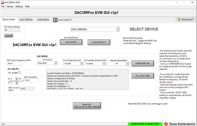
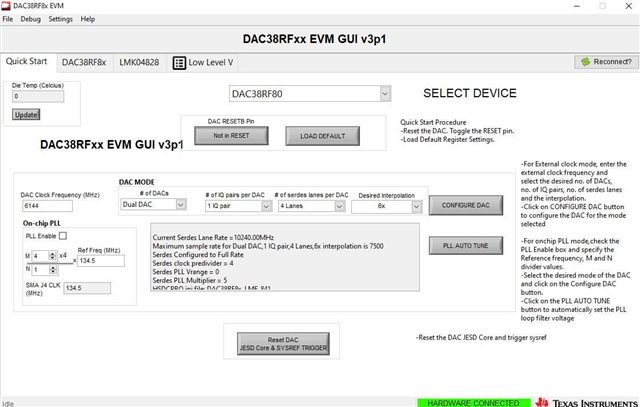
I am conducting an experiment with the DAC38RF80EVM and TSW14J56 boards and I am having an issue which I do not know how to fix.

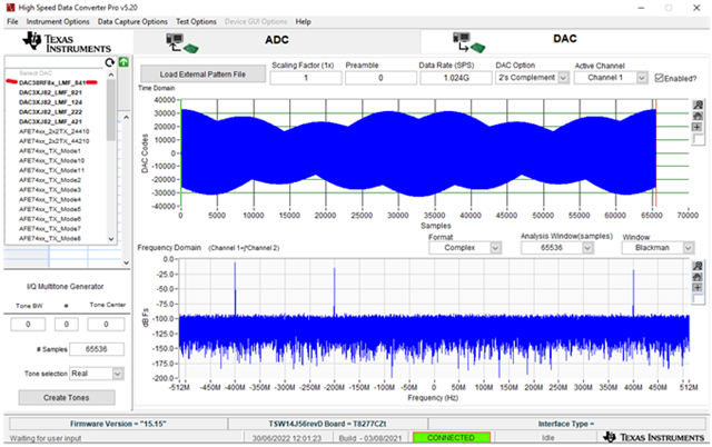
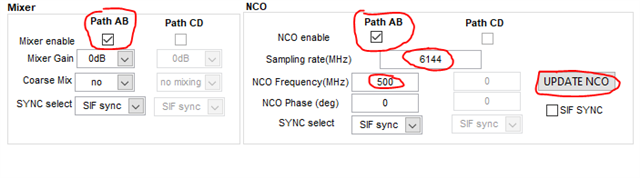
I am using these devices to make an experiment in which I use a MATLAB code to send tones through to the board. However I do not see any tones on the output spectrum

I am using a HSDC pro to send these tones into the board but I do not receive any output from the HSDC pro

these are the codes that I am using and are responsible to generating the tones for the HSDC pro

Fies.zip 

Regards,

Danilo

  • Danilo,

    Please makes sure the 5V supply to the TSW14J56EVM can source 4 Amps. Can you send screen shots of both the DAC GUI and the HSDC Pro GUI showing your setup? What is the status of the LED's on the TSW14J56EVM? Does your setup work if using a tone created by the Multitone Generator in HSDC Pro GUI?

    Regards,

    Jim

  • Hi Jim,

    Thank you for your response. Please see the feedback of our customer below.

    Hello, thank you for getting back to me. The board is connected to a 5V and 4A supply. I have checked this. 

    These are the DAC38RF80EVM parameters I am using. I have set an NCO and programmed the HSDC too. I also see no tones when I use the tone generation function. Also I am aware that there is an LED that should be blinking however, I am not seeing that. 

    Regards,

    Danilo

  • Danilo,

    I need the LED status info on the TSW14J56EVM. Everything looks fine except in HSDC Pro GUI, you do not have the DAC38RF8x_LMF_841 selected as shown in the attached file. After you loaded the external file, you must then click on "Send" in HSDC Pro GUI then click on "RESET DAC JESD Core & SYSREF TRIGGER" on the DAC GUI.

    I have attached the test file I am using. This works with no problems on my setup.

    In the file attached, see if you can get a 100MHz tone out using the I/Q Multitone Generator. After entering the values shown, click on "Create Tones", then click on "Send". After sending data the data, click on "RESET DAC JESD Core & SYSREF TRIGGER" on the DAC GUI.

    Regards,

    Jim

    100MHz tone using I.pptxJIMDATA1.CSV

  • Hi Jim,

    According to our customer,

    I have selected that particular DAC.

    Thank you for the file. I have used this JIMDATA1.csv file before. The LEDs that are showing are D2, D3 and D8. They stayed continuously on.

    I also tried sending a tone using the multi tone generator but it didn't work. There is no output.

    Regards,

    Danilo

  • Danilo,

    Please have the customer try the attached test to verify the DAC EVM is receiving a proper clock. They can use 6144M instead of the 9GHz called out by the document.

    Regards,

    Jim

    DAC38RF82_NCO_only_setup.pptx

  • Hi Jim,

    Please see the update from our customer.

    I have tried using 6144Mhz and received an output of 500Mhz which is what my NCO is at. So this works.

    I have tried the method that you have stated and the single tone is visible when I verify there is a clock.

    any suggestions?

    Regards,

    Danilo

  • Danilo,

    In the DAC GUI, in the Digital (DAC A) tab, have the customer change the data format to 2's comp, and disable the Constant Input. 

     In HSDC Pro, create a 100MHz tone from the Multitone Generator and send this to the DAC. 

    In the DAC GUI, in the quick start tab, click on "Reset DAC JESD Core & SYSREF Trigger. There should now be a 600MHz output if the NCO is enabled and set to 500MHz.

    If this is all working, they should then be able to import the .csv file I sent and send this to the DAC.

    Regards,

    Jim 

  • Hi Jim, 

    According to our customer, he tried the instructions above but it didn't worked. Do you have other suggestions?

    Regards,

    Danilo

  • Can they get an output with the TSW14J56 using the multitone generator? If not, what is the status of the LED's on the TSW14J56 after the firmware is loaded? Also send a screen shot of HSDC Pro GUI after they click on "Send".

  • Hi Jim,

    Please see the feedback of our customer.

    You have asked me to try this and I told you it does not work. The only lights that show on the LED is D1, D3 and D8. I know for a fact that the D2 light should be flashing. I cannot send a tone through the generator either as it does not show on the board.

    Please let them know about the LED status as I feel this is important.

    Regards,

    Danilo

  • Danilo,

    D2 not blinking usually means the FPGA is not receiving a reference clock from the DAC EVM. I also need the screen shot I requested to further help trouble shoot this. Please also send screen shots from the DAC GUI LMK tabs.

    See if the customer can verify there is a 256MHz clock on either C29 or C32 of the DAC EVM. 

    Regards,

    Jim

  • Danilo, I've also set this up with different hardware than Jim's and have no problems with this. I too suspect the FPGA clock is not set correctly. If the customer can send all of the LMK GUI tabs as Jim has requested then I will take a look at this tomorrow.

    Regards, Chase

  • Hi Jim,

    Our customer shared the screenshots below.

    Regards,

    Danilo

  • Danilo, I need to see these highlighted pages from the customer. The values below do not correspond to this particular configuration.

    Regards, Chase

  • Danilo, I forgot to ask, is the customer only applying the 6144 MHz clock to J1 or are they supplying the FPGA reference clock to J4 of the DAC38RF80EVM also?

    Regards, Chase

  • Hi Danilo, just a reminder about these images. If the customer can provide these we will be able to help.

    Regards, Chase

  • Hi Chase,

    I apologize for the delay, I just received the screenshots from the customer.

    Regards,

    Danilo

  • Danilo,

    On the PLL2 configuration page, the VCO Mux is set to External VCO, meaning Clkin1 input goes to the output dividers which is correct, but on the PLL1 configuration page the CLKin1 Out Mux is set to PLL1 so the clock is not being provided through External VCO. The customer has to tri-state the PLL1 charge pump and also set the CLKin1 Out Mux to the correct value.

    The output dividers stage looks ok since 6144MHz external DAC clock / 4 (through external hardware division) = 1536MHz which is passed to the clock dividers via External VCO and the FPGA clock will be this 1536MHz / 6 = 256MHz.


    Regards, Chase

  • Hi Chase,

    Please see the feedback of our customer.

    I have tried this but it is already like this and it still does not work

    The status of the LED's is still the same and I am receiving no output

    Also when I try to connect the HSDC it disconnects for some reason

    After this message, it says HSDC is disconnected

    Regards,

    Danilo

  • Danilo,

    What is the current rating/limit of the power supply for the TSW14J56? I will check the exact setup in the lab tomorrow and provide a configuration file for the customer to use.

    Regards, Chase

  • Hi Chase,

    According to our customer, the current rating is 4 amps at 5V

    Regards,

    Danilo

  • Danilo,

    I will create a config file for the customer to load onto their EVM. I will try to have this done by tomorrow.

    Thanks, Chase

  • Danilo, since we've taken this thread to email I will close this thread. Thanks