This thread has been locked.

If you have a related question, please click the "Ask a related question" button in the top right corner. The newly created question will be automatically linked to this question.

Using dsp_mcbsp to conmmunicate with ADS1298?

Other Parts Discussed in Thread: ADS1298

Hi qw,

The ADS1298 device should not get 'a little hot' - is you reference slowly declining as the temperature of the device increases?  I suspect you've damaged the device somehow.  This is not normal behavior.  The /CS signal needs to be low through an entire command cycle.  If you do SDATAC, dropping /CS and sending the command is fine.  The RDATAC and data retrieval can all be done under the same /CS cycle - you do not need to raise it in between.

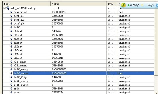
The internal DC tests depend on which channel you are looking at, this is described in the data sheet at the top of page 24, channels 1, 2 and 5-8 are 1/2 AVdd; channels 3 and 4 are 1/4DVdd.  The major influence here is the reference and the quality of your supply voltage.

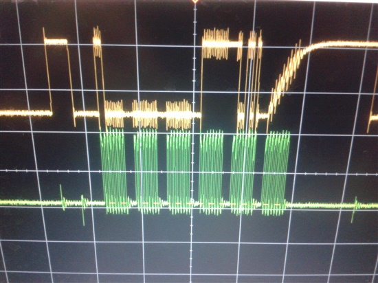
Both interrupt routine are located in t1298_ob.c.  For the clock and data - you mentioned very early on in this thread, you had the ADS1298 working with STM32 via SPI - there really is no difference here with the McBSP.  In clock stop mode, to generate clocks you must put something in the transmit buffer of the master controller.  To simply generate 24 clocks to read data, load the transmitter with 0x000000.

  • Hi ,Tom.

    Tom Hendrick said:
    I suspect you've damaged the device somehow. 

    I am sorry to hear that.However,i change  the data rate from 500SPS to 2kSPS,there is a change on the  DRDY pin ,and still there is a 1.2 v ---2.048MHZ  internal clk out of the clk pin. And also the strature of the data from the SPI_OUT pin is like 1100  0000 0000 + channel data.Could this  represent something?

  • Hi qw,

    I've split this thread off to a new one simply because I believe we are now dealing with hardware problems.  On the original thread, I asked you to please post a schematic showing your hookup of the ADS1298 to your C6713 McBSP.  I don't believe you ever did that, so if you can forward the schematic now, that would be a good place to re-start this discussion.

    Initially you got the internal clock out but at only 800mV.  Now you have the internal clock but only at 1.2V and your reference voltage is falling off from 2.4 to 0V.  If the communication sequence gets corrupted, you may reset the ADS1298 or inadvertently change the configuration register settings.  When you see problems, please re-verify the registers are the way you set them originally.  If the communication gets out of sequence somehow, you can re-set the serial interface by toggling /CS and re-sending your commands.

    You also mentioned that the ADS1298 gets hot.  Perhaps you can monitor the AVdd, AVss and DVdd lines with an ammeter to see where the current is coming from.  That may help track down the source of that problem.

  • Hi, Tom

    Very glad come back to this program.

    And there is good news. Firstly, the ADS1298' temperature is ok, never hot like before. Secondly, I can get the internal clock out of the CLK pin, also the frequency is correct--2.048MHZ. Thirdly, I get the DRDY frequency is 2KHZ as my configuration is CONFIG1_dr=100. And I also get 2.4V voltage of the VREFP pin as my configuration is CONFIG3_VREF_4v=0 (2.4v reference voltage).

    It’s said in the PDF p38 that “If no data are retrieved from the device, DOUT and DRDY behave similarly in this mode”. Here is 2KHZ pulse_ _ low (0) long, High (1) short. My problem is when I use while (1) to read data continually there is no data come out from the SPI_OUT. And I found that the DRDY didn’t change to low (0) short, High (1) long. And the SPI_OUT is the same, pulsed at 2KHZ like DRDY. I put the START pin to high and send the RDATAC command before the while (1) loop. I have seen others post very clearly about DRDY. I found that DRDY should connect to a external interrupt pin of the DSP like EXT4-EXT7. In my project I just connect the DRDY to a GPIO pin which is input. And in my while (1) loop I just send 24-bits 00 to ADS1298 then polling the RRDY to receive the data. Am I right?

    So in this case I only can receive data using RDATA command, not continually. So must I connect the DRDY pin to an INTERRUPT PIN?


  • Hi there Qin Wei!  Welcome back!

    I'm happy to hear that you've made some progress with the ADS1298!  Please double check that you are referring to the latest data sheet, if I'm not mistaken, the passage you are referring to above is on page 41, under the RDATAC heading.  With DRDY tied to a GPIO pin, you would need to use polling to determine the state of the pin.  Once it went low, you would need to generate 24SCLKS * Number of Active Channels + 1.  Assuming you have all eight channels in use, that would be a total of 216 clocks.  You have to ensure you got all of that data retrieved within 500us (the period of the DRDY pulse) or you can start getting corrupted data and may see strange things on the DRDY output line.  It's not necessarily a requirement that you connect DRDY to an interrupt, but it certainly is a more efficient way to interface with the McBSP.

  • Hi, Tom

    Yes, the message which I take about the DRDY is under the RDATAC heading. Of course I used polling to check the DRDY (connected to a GPIO_PIN), just like this:

     “if(!(GPIO_pinRead(hGpio,GPIO_PIN10)))”.

     And then I send 0x000000 to the ADS1298 to get the data back from ADS1298, just like this:

                                     “while(!MCBSP_xrdy(hMcbsp0));

                                     MCBSP_write(hMcbsp0,(Uint32) ADC_READFROM_ADS1298);

                                     while(!MCBSP_rrdy(hMcbsp0));

                                   temp = MCBSP_read(hMcbsp0);”

    Here ADC_READFROM_ADS1298 is 0x000000 or Oxffffff.

    Aha, I know if I used 8 channels I should send 216 clocks. Here I just use one channel. Channel one configure is 0x05, others is 0x80. Am I right of the channel configuration?

    You know only the above code just receive the status, after this I send another 24 bits 0 to the ADS1298 to get the real data from the ADS1298 channel one.

    However, I found DRDY also like I told above, just “low (0) long, High (1) short” at 2 kHz pulse, like the SPI_OUT pin.

    So where is the problem?

  • DRDY should return high with the first falling edge of your SCLK while collecting the STATUS word.  Can you post a screen shot of your SCLK, DRDY, SDI and SDO?

  • Hi, Tom

    I think my DRDY don’t return high with the first falling edge of my SCLK while collecting the STATUS word. I found that when I stop my project, the program stopped at “  while(!MCBSP_rrdy(hMcbsp0));”. I debug the project step by step I found that my MCBSP_REG_SPCR didn’t change in the RRDY bit, although my RRST bit is 1.


    The pictures below are taken by my mobile phone.

    Picture one: channel one is DRDY, channel two is SPI_OUT

    Here is a small part of the picture one:


    Picture three: Channel one is SPI_OUT, Channel two is SPI_IN. you can see that the SPI_IN is always high here. The pulse of SPI_IN is because I don’t connect GND of the probe with the GND of my board.

    Picture four: channel one is CLK pin , channel two is DRDY.


    Below is the small part of above:


    SPI_CLK is always low, because I think my project stop at “   while(!MCBSP_rrdy(hMcbsp0));” as I said above. And I don’t know why my DRDY doesn’t change to high when I send the some bits 00 to ADS1298 in order to generate SPICLK for ADS1298 to send the DATA back to DSP.

    And my VREFP is 2.4V; I can check the voltage of the VREFP pin. It’s correct.

    and i can get the device id_92, and loff_sensp and loff_sensn are 00.

     here i only check out those three regs , others not.

  • Hi, Tom

    Are you still there? Could you give me some advice?

    Or anyone else could solve this problem? Please tell me how to do it ?


  • Hi Qin Wei,

    If I understand your problem correctly, your DSP goes idle at your while(!MCBSP_rrdy(hMcBSP0) because it has not actually received anything.  The ADS1298 needs you to send it an SCLK so it can send data into the receiver, which would generate the the receive interrupt.  DRDY is toggling as if there is no attempt to retrieve data. 

    Have you tried putting DRDY into one of the external interrupt pins?  If you want to zip up your entire project and post it here, I can try to look at that for you.

  • Hi, Tom

    There is good news that I can read data back from the ADS1298. The problem which I told before maybe was because the BUFFER size which used for my receiving data storing. You said that “The ADS1298 needs you to send it an SCLK so it can send data into the receiver, which would generate the receive interrupt.” Here, I put start pin to high , send RDATAC command , then check the DRDY signal, when DRDY is low,

    using “while(!MCBSP_xrdy(hMcbsp0));

                                     MCBSP_write(hMcbsp0,  ADC_READFROM_ADS1298);” to send 8bits SCLK here needed for the receiver. ADC_READFROM_ADS1298 is 0x00u. Then I used “                              

    while(!MCBSP_rrdy(hMcbsp0));

                                   temp = MCBSP_read(hMcbsp0) ;” to read back 8bits convert data. And I do six times like this: send 0x00, receive 8bits convert data or the status. So you can see I send the sclks which needed in receiving data from ADS1298. I used internal test signals which ADS1298CONFIG2 is 0x0011; I got FF9A00 and 3D which is HIGH and LOW voltages.

    However if I change the MCBSP to send and receive 24bits, and the ADC_READFROM_ADS1298 is 0x00000000u, the data which I receive is nothing else but 0. in that case i just need to seed 2 *24bits to read back the covert data. But the result is wrong.You can see the DRDY change to high. I don’t know why? You see I used 8bits is currect.

    And another good news is the configure regs which I read back is correct.

    However I still have two problems. One is that when I want to read the convert data I need to send the SCLKS to ADS1298. Is there some delay between them? Another is the start pin and the cs pin. If I put the start high, the DRDY change to high when the master DSP send the sclks needed for the read back convert data. Here start can I used a TIMER to connect it, so that I can receive fixed length data, for example, 65536 samples. Am I right?

    Lastly if I used interrupt and EDMA, is the order right? Connect DRDY to EXT4 pin. When I put the START pin high, and then just wait the interrupt happen. In the interrupt function used EDMA_CHANNEL4 which synchronize with the EXT4, sending 6*8bits 00, meanwhile used EDMA_CHANNEL 13 which synchronize with the MCBSP0_REVT to receive convert data.

  • Another question is that when i used internal test signals, my HIGH or LOW convert data didin't change at the low bits, just FF9A00 or 00003D. Is it right? or when i used internal  DC test signal ,  in theory the covert data is ? FF9Axx or else?


  • I'm glad to hear you have made some progress! 

    Technically, you can tie the START pin high and simply send the START command.  You could also use a TIMER, and your process sounds correct. There really is no reason why you should not be able to send two 24-bit frames to the ADS1298, so I don't know what the problem might be there.  Perhaps you have the receiver and transmitter set to different bit lengths?