This thread has been locked.

If you have a related question, please click the "Ask a related question" button in the top right corner. The newly created question will be automatically linked to this question.

ADS131M06: Environmental noise immunity

Part Number: ADS131M06

Hello,

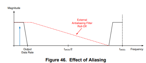
The company I am working for is using the ADC ADS131M06 for sampling the output of a current transformer (CT) that has an integrated burden resistor, therefore outputting a voltage of 0.333V over relatively long twisted wires of around 1m. When the CT is used in a noisy industrial environment, the output of the ADC is corrupted by environmental RF noise, most probably due to motor drivers (VFDs) located nearby. Other channels used for sampling the high-voltage (with a resistive divider) are not affected by this noise, indicating the noise is likely coming from the CT cables and not from the PCB itself. The signal of interest is located between 1Hz and 10kHz, the noise is in the range of 20-100kHz. The electrical design that is used today between the CT cables and the ADC can be found in attachment.
- Can something be done on this circuit to improve the noise immunity? 
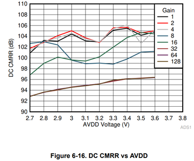
- For now, we use the PGA with a unity gain, while we could go to a gain of 2, maybe 4. Would increasing this gain be beneficial in our situation? My guess is it will also amplify the noise...

Thank you very much in advance.

Best regards,
Nicolas Verbeek

  • Hi Nicolas,

    Opening thoughts:

    The rule of thumb I was taught, when it comes to environment noise, is to dampen the source (this case, the motors) first and then try to isolate second. In other words, something like physically moving the wires away from the motors as far as you can to see if the noise can go down. VFDs are tricky because you don't have much to change to dampen its behavior. Where other motors I might be able to change a PWM frequency and trade off power consumption for this kind of noise, or something else. If you can think of a tradeoff with altering the VFDs to fix the issue, I recommend you start there.

    Waveform to distance conversion says that your 1m wires are susceptible to 300MHz (and up to the 20th harmonic to be safe, which is around 15MHz) to act as an antenna. Would I try making the wires longer so that I can better route away from the source first, but trade off making a lower frequency antenna? Absolutely, >1MHz is still so far out of the range you'll have the make the wire really long for it actually to affect the circuit. I acknowledge a cost trade off but it might be less that some of the other components you might need.

    Also, if you have twisted pairs, you're telling me that this is unshielded twisted pairs (at least I hope or the extrinsic noise is really bad). The next line of defense after isolation is sealing (or shielding), and finally filtering. As a experiment, could you find some twisted shield pair wire and replace it one system to see if the noise goes away? Nice to prove your hypothesis right and have a back up plan if we can't fix the problem with filtering (more on that later).

    Changing the input filter:

    Normally, I'd recommend reducing the sampling rate but you have a bandwidth pretty high in frequency so its not really an option. In reality your first option is to change the input filter and the second is to develop some digital filtering. Doing an FIR, if you can handle the delay, or adding another SINC (moving average of samples) lower in frequency compared to the ADC could help with this issue.

    Otherwise, I'd add some resistance on the input to help move the common mode filter down in frequency and lower the differential one as well. You could stand to make the common mode caps at 100pF and see if there's improvement. In reality, the noise is really close to your frequency of interest and upgrading passive component tolerances might be necessary and might bump up cost more than your other methods, so be weary of that. 

    Small note about gain, yes, gain usually makes noise worse and more prominent.

    Best,

    -Cole

  • Hello Cole,

    Thank you for your complete answer. I will try to answer following the same structure.

    Opening thoughts
    - Unfortunately, I cannot act on the environment itself.
    - I'm not sure I follow you here. The noise is coming from VFDs that have a switching frequency of say 4-16kHz. Wouldn't increasing the wire length make me more susceptible to noise by coming closer to the fundamental frequency of the VFD? Intuitively, I would want to make my wires shorter to limit the noise.
    - I do indeed have unshielded twisted pairs. I did some tests with shielded twisted pairs and the noise is reduced, but not completely removed either.

    Changing the input filter

    - Actually I'm not sure of the efficacy of my common-mode filter circuit in its actual shape. Wouldn't it be better to have the kind of topology described in this topic: e2e.ti.com/.../faq-delta-sigma-adc-anti-aliasing-filter-component-selection , i.e. a single resistor on each input with a capacitor to ground and to the other input ?
    After some thought I'm not sure about the "true" frequency of the noise either, I might catch very high frequency noise but aliased since it is sampled at 32kHz. A well-designed common-mode analog filter might filter this.
    - Regarding the higher gain, does increasing the PGA have any effect on the CMR? Or will it simply amplify the (common-mode) noise and the signal?

    Best regards,

    Nicolas Verbeek

  • Hi Nicolas,

    - I'm not sure I follow you here. The noise is coming from VFDs that have a switching frequency of say 4-16kHz. Wouldn't increasing the wire length make me more susceptible to noise by coming closer to the fundamental frequency of the VFD? Intuitively, I would want to make my wires shorter to limit the noise.

    It sort of depends. I meant to say if making the wires shorter puts them physically closer to the VFDs, then I'd recommend trying to make the wires longer in an attempt to physically move them away from the VFDs. The equation shows that your 1m of wire isn't a good antenna for picking up the noise in the frequency band you've pointed out. Moving the wire away (which reduces the amplitude of the incoming noise signal) will be more effective in reducing the overall noise in that frequency band than making the wires shorter. Hope that makes sense.

    - Actually I'm not sure of the efficacy of my common-mode filter circuit in its actual shape. Wouldn't it be better to have the kind of topology described in this topic: e2e.ti.com/.../faq-delta-sigma-adc-anti-aliasing-filter-component-selection , i.e. a single resistor on each input with a capacitor to ground and to the other input ?

    I agree that filter topology was better but I was under the assumption you couldn't change your schematic, only depopulate or replace components. If you have the ability to follow the advice in the post, I suggest that.

    After some thought I'm not sure about the "true" frequency of the noise either, I might catch very high frequency noise but aliased since it is sampled at 32kHz. A well-designed common-mode analog filter might filter this.

    For aliasing I like to use this picture (its from a different datasheet):

    As a reminder, the f_MOD of the ADS131M06 is something like ~4MHz and your cutoff is something in the ~100kHz (if memory serves me right) range so we should have quite a bit of attenuation for anything to alias back.

    I have seen customers using chopping, while is kind of like another modulation, and seeing aliasing of lower frequency signals:

    You can use the equation there and do the inverse to find the chopping frequency and see where it lands. Given you're at a low OSR, the frequency will probably be out of pass band though.

    - Regarding the higher gain, does increasing the PGA have any effect on the CMR? Or will it simply amplify the (common-mode) noise and the signal?

    In short yes but its relatively the same for low gains and lower (worse) at higher gains (>8). That being said, you can probably do some quick math and see that some other source of error will be pretty small compared to something else like offset (picture below from TI Precision Labs video training series: https://training.ti.com/ti-precision-labs-adcs-ac-dc-specifications-offset-error-gain-error-cmrr-psrr-snr-and-thd?context=1139747-1140267-1128375-1139102-1128657

    Best,

    -Cole

  • Understood! Thank you very much for you help.

    Best regards,

    Nicolas Verbeek