This thread has been locked.

If you have a related question, please click the "Ask a related question" button in the top right corner. The newly created question will be automatically linked to this question.

ADC3683EVM: HDSC Pro freezes in bypass mode

Part Number: ADC3683EVM
Other Parts Discussed in Thread: ADC3683, CDCE6214

Hello,

when trying out the ADC3683EVM with TSW1400 I noticed the following issue:

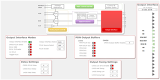
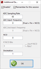
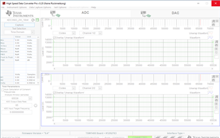
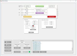
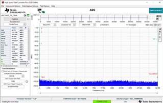
  • 2 wire mode, real decimation with factor 2,4,8,16,32: works without any problem (see screenshots of settings and results attached)


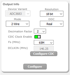
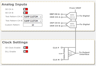
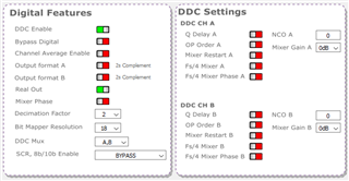
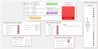
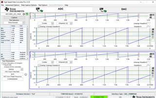
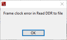
  • 2 wire mode, bypass mode: High Speed Data Converter Pro Software freezes when capture button is pressed and has to be closed (see screenshots of settings attached)


Please advise, if some settings were selected incorrectly and how to get the setup running in this configuration.

Thank you in advance and best regards,

Lukas Huber

  • Hi Lukas,

    Give us a few days, we are looking into this for you.

    Thank you,

    Rob

  • Hi Lukas,

    When you mention that HSDC Pro 'freezes' when the capture button is pressed, do you see any errors that pop up? Additionally, what .ini file are you using in HSDC Pro?

    Regards, Amy

  • Hi Amy,

    I'm using the ADC3683_2W_18bit from the dropdown menu in the top left corner.

    The window goes to grey and the (no response) is shown in the header.


    I usually close the software at this point manually, but if you wait for a really long time, sometimes there comes this error message:

    Best regards,
    Lukas

  • Hi Lukas,

    How did you get the HSDC Pro screen to duplicate the ADC codes view? I just noticed that in your configuration for bypass mode, you opened the 'cog wheel' option and selected 'enable'. For bypass mode you need this feature disabled.

    For bypass mode to work, try only this steps:

    ADC35XX GUI:

    1) Open the ADC35XX GUI (as you show in your first picture). The device variant should automatically load if the board is properly connected.

    2) Select 18b, 2w mode, bypass. Toggle the CDC Clock enable to 'on' and select the full sample rate.

    3) First click the 'Configure' button at the bottom, and then select the 'Configure CDC' button. Check that the PLL_LOCK LED (D1) is on to ensure CDCE6214 has been configured correctly. Doing this out of order may be the cause of the frame clock error you see in HSDC Pro.

    Note: Do not change any other GUI settings. Everything should be set correctly by default.

    HSDC Pro:

    1) Load the ADC3683 .ini file (as you have shown in the figure)

    2) Select Capture, and you should see an output

  • Hi Amy,

    thank you for the explanation!
    So in HSD ProC I just need to enter 65MHz into the field left of the cog wheel and in the ADC35XX GUI everything should be preconfigured correctly, even if e.g. in the output interface window by default the output interface switch is set to disabled, the output interface select is set to DDR and tin he output interface mapper all drivers are disabled?

    I will try the workflow described by you as soon as I'm back in office this week and get back to you with the results.

    Best regards,
    Lukas

  • Hi Lukas, 

    Yes, that is correct - just enter 65M in the field to the left of the cog wheel in HSDC Pro.

    If you plan to use onboard clocking, the DCLKIN frequency will configure once the 'configure CDC' button is clicked in the ADC35XX GUI. If you opt to use external clocking, just toggle the 'CDC Clock Enable' off, and type in your desired sample frequency (i.e., 65M). The correct DCLKIN frequency will display if you click 'calculate', and you would set a second signal source to this frequency. 

    To answer your question about the output interface (referring to page 55 in the ADC3683 datasheet):

    'Output Interface Enable' and 'Output Interface Select' are controlled by register 0x07 - which as you have noted reads 0x00 by default. The datasheet indicates that 'After initial reset the default output interface variant is loaded automatically from fuse internally. However when reading back this register reads 000 until a value is written using SPI.' for this register. 

    This means that while the readback for this register is 0x00, by default the part is internally loaded from the fuse to the corr  
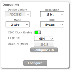
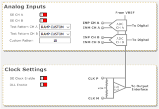
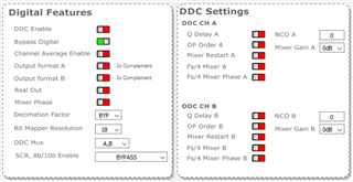
ect default state. Try matching your GUI and HSDC Pro settings to the screen shots below and let us know if you continue to have issues running in bypass mode.

    Regards, Amy