This thread has been locked.

If you have a related question, please click the "Ask a related question" button in the top right corner. The newly created question will be automatically linked to this question.

DAC53204: SPI Programming mode

Part Number: DAC53204
Other Parts Discussed in Thread: DAC63204

Hello, 

Regarding SPI Programming mode at 7.5.1

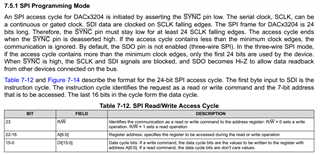
The slot for the register address is 7 bit long but register address is 8 bit long, example (table 7-21):

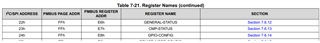
Do we need to chump the MSB in the address ?


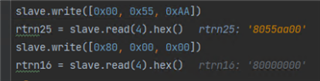
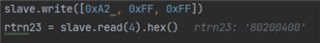
Can you please send us read/write example ?

Thanks,

Ariel

  • Illia will answer this today. Thanks!

  • Hello Ariel, 

    The sequence to perform SPI would be:

    First bit: 1/0 for read or write, the last 7 bits would be address of the register you are writing to, which you can find on that table. So, the whole sequence would be 8 bits.

    Does this answer your question? 

    Thank you, 

    Illia Volkov  

  • Hi Illia,

    We are using the DAC63204 driving by FTDI FT4232H with SPI protocol (Mode 2).

    in hardware terms - all the SPI lines connect with PU to the IO voltage level.

    we are wondering if we are using the right command to read any data from the DAC.
    for example, we transmitted the command 0xA2,0x00,0x00 (pic 1) to read the config register data (0x22 address)

    as you can see in pic 1, the MISO line stays high

    pic 1 at the following link:

    Yellow - CS

    Blue - MOSI

    Pink - MISO

    Green - CLK

    Could you please give an example of a valid read command and a valid write command? 

    https://imgur.com/a/T0ZVGcU

  • Illia is reviewing this now.

  • Hello Ariel, 

    I am not that familiar with this specific scheme. Could you please clarify on what are the additional parameters of the function? I understand that 0xA2 is the 8-bit data you are trying to sed, but what are the other null parameters you are trying to send?

    Thank you, 

    Illia Volkov 

  • Hello Illia,

    Im Ariel colleague.

    The 0xA2 is the read bit + the address of the configure register follow by dont cares (table 7-21 in the datasheet),  we are trying to read register but we are not getting anything on the miso line of the SPI

    Our question was to verify that we are sending the right command for the read register according to the datasheet table 7-12 ( or in the original question)

  • Hello, 

    Just to confirm. By default, DAC has 3-wire SPI communication. The readback capabilities are only available if you configure GPIO as an SDO pin ( MISO ). If not, please configure GPIO as a SDO and try again. Instructions are on the bottom of page 44 of the Data sheet.

    Thank you, 

    Illia Volkov 

  • Hello Illia,

    Thanks ! this solved half of the problem im now able to write register and verify them but in still having problems when i try to read registers.

    Im using the NOP register, section 7.6.1 , when im writing 0x55AA the echo is what i can read from the SDO bit when i try to read it im not getting the register value.

    for write i use write command 0x0055AA to read im using 0x800000 as the datasheet describe in table 7-12 but the data shows all "0"

    See Below picture for the execution

    rtrn25 is read after write 

    rtrn16 is just read (bit 23 is set to 1 bit 22-16 is the address the rest 16-0 are dont care)

    please advise.

  • Hello Idan, 

    Could you identify to me what are you attempting to read/write and to which registers? I do not believe that 0x55 is an address to any of the registers. 

    Regarding NOP register. It is read only register, so you cannot actually write anything to it. So, if you try to read from it, the value would always be "0".

    Thank you, 

    Illia Volkov 

  • I'm trying to verify my read command with a register that won't effect anything, sorry i missed the fact that its a read only register.

    So lets look at a different register, the  7.6.12 GENERAL-STATUS register address 0x22, the return value is 0x200400 and its not align with the data sheet device id bits 2-7:

    0x200400 = 0010 0000 0000 0100 0000 0000

    Is this correct ? i dont think that this is right.

  • Hello Uliel, 

    General status is also read only channel. 

    The easiest way to check read/write would be to write to DAC DATA register. Try to write to 0x40 register 0x800 and see if you can read that back.

    Also, could you do me a favor, and connect your communication to oscilloscope, and send me a snip of it so I can see all of the signals in attempt to debug.

    Thank you, 

    Illia Volkov