This thread has been locked.

If you have a related question, please click the "Ask a related question" button in the top right corner. The newly created question will be automatically linked to this question.

ADS131M08: ADS131M08-Multiple ADC not working

Part Number: ADS131M08
Other Parts Discussed in Thread: ISO7762, SN74LVC2G125

Hi Team,

I have connected 2 ADC with one MCU as per below configurations.

When we tried to read ADC, only one ADC is reading and other is not?

ADC: ADS131M08

Isolator: ISO7762

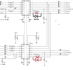
Schematics Snapshot:

Can you please help why it is happening?

  • Hello Deepak,

    You're read both devices separately? But when you run the routine to talk to both of the devices, it doesn't work? Or you've only ever talked to 1 ADC?

    I'd probe the SPI lines of the two devices, specifically the CS lines, and see if there's any bus contention. There's no reason for you to look at one and then not speak to the other.

    Also noticed that SYNC isn't the same line for (assuming I can read the poor resolution picture correctly), I don't see a reason for this and it can also contribute to the problem if you're trying to synchronize the two devices. Having a cleared FIFO and knowing when DRDY will trigger leads to predictable communication with the device.

    Best,

    -Cole

  • Hi Cole,

    Both Slaves are working independently..

    I have removed R60 resistor one of the ADC worked.

    When i removed R278 resistor then second ADC worked..

    But when both R60 and R278 populated, SPI communication is not working.. we are not getting anything on MISO lines (CLK, MOSI and control signals are well)..

    Is it because of iso7762 output type problem.. like iso7762 is push pull? It could be because when one of the devices trying to send MISO signals others devices could be pulling it down so controller is not getting anything..?

    What do you think?

  • Hi Cole..

    Both devices are working independent and Synch is common at controller END. 

  • Hi Cole,

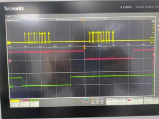
    I tried to capture WF at MCU end, I dont see CS Bus contention here (Attaching for your reference).

    i tried to capture data on MCU END for MOSI... We dont see required amplitude here 

    Amplitude: 2V to 2.3V.. i dont know why.


    Let me know if you need more information.

  • Hi Deepak,

    This looks like a bus contention issue to me, at least for MOSI. 

    Is it because of iso7762 output type problem.. like iso7762 is push pull? It could be because when one of the devices trying to send MISO signals others devices could be pulling it down so controller is not getting anything..?

    This result is a good find. In general, I agree, if one line is high and line is low you will have some contention. In context of the ADS131M08, DOUT (or MOSI) would be in a high impedance state but, to your point, the ISO devices can't seem to do that. That all being said, just use an oscilloscope and probe the voltages before the isolator and after the isolator to confirm your hypothesis but I definitely think that the contention is what is happening.

    Have you seen our reference designs? Here's a reference design for One-phase shunt electricity meter reference design using standalone ADCs https://www.ti.com/tool/TIDA-010036 Because the other end of neutral is GND, the local MCU is on the hot or high voltage side of the isolation barrier.

    In short, I'm not a isolation expert, but I can't tell you if there's another device that can go high impedance to prevent this kind of issue. I suggest posting on the isolation E2E for with the part number you have an explain the problem. They might be able to give you a different part number. Using a MUX could solve this issue as well if the line CS can be tied to the channel (or ADC) you're reading from. Or maybe looking into having a localized MCU on the high voltage side of the isolation barrier as shown in the reference design. 

    Best,

    -Cole

    P.S. Last time I saw this, there was a subroutine that accidently enabled a 1.8V pull up logic on an input for an external memory IC at the same time data was pulled from the ADC. I suggest you take look at the MCU side and make sure something like that isn't occurring if all of this turns about to be wrong.

  • Hi Cole,

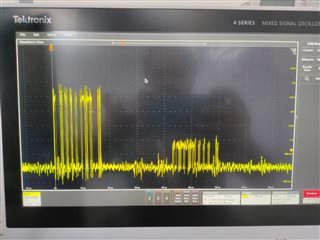
    My Mistake: Yellow WF is MISO (Master in Slave Out) and it is measured at U5.7 wrt U5.8 (Waveform at U5.10 wrt U5.9 are clean)

    Sharing snapshot for better understanding.

  • Hi Cole,

    How it would look if we place diode next to U5.7 and U4.7 (they will not pull each other).

    Can you please help here Diode selection here?

  • Hi Deepak,

    I don't think I've ever seen anyone do that but it could work. Let me see if I can loop in the isolation folks to see if they see any issues with it before moving forward.

    Best,

    -Cole

  • Thanks Cole.

    Hi Deepak,

    Like we discussed earlier, like Cole also already pointed out, two push-pull logic outputs shouldn't be directly connected together. This leads to VCC/GND short when one of the output goes HIGH and the other goes LOW. One output sources current and other sinks, the actual current can also be large if there is no series resistor.

    When a series resistor is used, the current can be limited but the actual voltage observed on the output pins can be intermediate voltage which is neither HIGH nor LOW. This also shows up in your waveform.

    The best way to address this issue is to use digital isolators with output enable control, please refer to the below FAQ on multiple isolator connection to MCU.

    https://e2e.ti.com/support/isolation-group/isolation/f/isolation-forum/991655/faq-how-to-connect-spi-mcu-to-multiple-isolated-spi-nodes

    I understand that you require 6 channels on each device and that's the reason you had to choose a 6-channel device which doesn't have output enable control. In this case, one other to best resolve the issue is to use MOSFETs at the output of digital isolator to convert the push-pull outputs to open-drain outputs. Open-drain outputs can be tied together without any issues and using one common pull-up resistor. But the pull-ups can limit the maximum datarate that you can operate at.

    You could also implement output enable control by using tri-state buffers connected at the output of digital isolators.

    I hope this helps you with all the inputs and options that you would need to resolve the issue. Let us know if you have any further questions, thanks.


    Regards,
    Koteshwar Rao

  • Hi Koteshwar and Cole,

    Thanks.

    Koteshwar: Can you please help me with tristate buffer for the same from TI

  • Hi Deepak,

    I am from the isolation product group, it is best to get the device recommendations from the experts in Logic forum from the link below.

    https://e2e.ti.com/support/logic-group/logic/f/logic-forum

    You could also look for the devices on TI website and choose the one the best suits your application. Since you require 2-channels to be tri-stated, I did a quick parametric search on logic products page, filtered them to show only devices with 2 channels and sorted them in an ascending order of price. You can see that list below,

    https://www.ti.com/logic-voltage-translation/buffers-drivers-transceivers/noninverting/products.html#p480=2;2&p116=3-State&sort=p1130;asc

    The first device in the list is SN74LVC2G125 which might also work for your application.

    https://www.ti.com/product/SN74LVC2G125

    Let me know if you have any other questions, thanks.


    Regards,
    Koteshwar Rao