This thread has been locked.

If you have a related question, please click the "Ask a related question" button in the top right corner. The newly created question will be automatically linked to this question.

DAC8741H: SPI Comms Issues Part II

Part Number: DAC8741H

Hi,

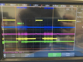
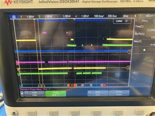
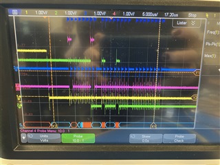
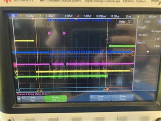
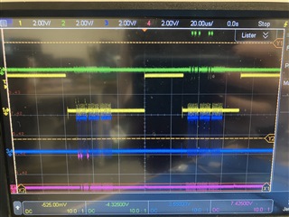
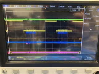
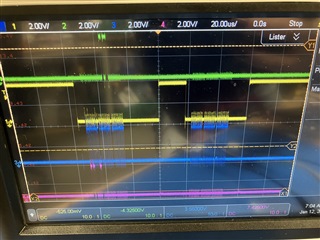
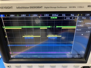
I previously asked a question about communicating over SPI with the DAC8741, which resulted in getting the expected communication. However, revisiting my PCB and code snippet, I am getting completely different results. I send [82,00,00] to read the Control register - the first time I run the code snippet, I get back all 0s, the second time I get a series of random numbers that is different every time I reboot. It seems as though the device is responding, but not on the correct clock cycle (the times I get back all 0s, I can see comms on the SDO line, but they are within the 3 bytes of the send message, the times I get back random numbers, they seem to be not synced properly). Additionally, sometimes it seems that the SDO/MISO line is getting stuck high, or remaining high throughout the message. I have tried multiple different messages, both read and write, to different registers. I have also attempted sending [07,00,01] to Reset all registers, with the same result. I'm still using a Raspberry Pi 4, my PCB is still the same as the previously attached schematic, and I'm still using writebytes and readbytes from the spidev library. I have tried with two different PCBs to verify that the DAC8741 itself is not the issue. I've attached my scope photos below, and would appreciate any debugging suggestions ASAP. Also would be glad to jump on a call with an apps engineer.

Note in the images, yellow is CS, green is SDO/MISO, pink is SDI/MOSI, blue is SCLK.

Thanks!

Libby

H2Ok Innovations

  • Libby,

    For verifying the SPI, let's start with something simple. The MODEM IRQ MASK register (21h) at startup should have a default value of 0x0024. Start by just making sure that you can read that. For this device, I think the read would start with a frame of A1 00 00 and then to read it back you would send 00 00 00. (I'm pretty sure that's the reading, but you should verify that in the datasheet too).

    Keep the scope on to see the transmission and receive bits. Also, I'd align the grounds so that they're about separated with 2 divisions on the screen, and set the signals to 2V/div. It'll be easier to read that way.

    If the data comes back as 0x0024, let me know that the read came back ok. After that, I would send a write to the device to change one bit. Then read it back the same register. If that works, you should have the communications working. If something comes back wrong, let me know.

    Joseph Wu

  • Hi Joseph,

    I sent A1 00 00 and read 3 bytes, the first time I sent it the Pi read the response as 00 00 00 (the first image with the SDO and SDI signals overlapping), the second time the response was 3 7d f0 (the second image).

    However, if I power cycle the PCB, the first time I send is 00 00 00, and the second time I get 60 81 00.

    I waited approximately 1 minute and tried again, and the second time send was 52 a 00.

    I've attached the scope photos.

    Thanks!

    Libby

  • Libby,

    Because of the inconsistent results, I think there might be noise in the communication. Do you think you can shorten up wires, and try to reduce the noise. Specifically, I think the noise might be coming from the SCLK and that might be disrupting the communications more than anything else. 

    If there is noise in the SCLK, the line may get a spike and that would be interpreted as an SCLK pulse by the DAC, while the micro hasn't sent one. In that case when reading back data, the clock gets advanced. When reading something like 0005 (with the last byte 0000 0101) and you get noise in the SCLK, you might read back 000A (0000 1010). Sending data might have the same problem, where device receives some other value than is what was intended.

    Again, you might want to clean up the wires to shorten them as much as possible. Adding a couple of pF of capacitance to clean up the SCLK might also help.

    Joseph Wu

  • Hi Joseph,

    The setup is largely the same as the last time I had the device working, but I did try to clean up the jumper wires. I'm getting the same results: when I power cycle the device, the first time I send a1 00 00 I get back 00 00 00, the second time 60 81 00, the third time 00 00 00, the fourth time 52 a 00, and after that alternating 00 00 00 and 52 a 00. I don't believe this is a noise issue as it is somewhat consistent, just not the message I should be getting.

  • Libby,

    I just noticed that the schematic is labeled with signals labeled with _ISO next to the SPI lines. Are you using some isolators for power or communication?

    Joseph Wu

  • Libby, 

    Based on our correspondence, it looks like you had some problems with the isolation between the micro and the DAC. When the isolation was bypassed the expected results came up.

    If you have any more questions feel free to post back.

    Joseph Wu