This thread has been locked.

If you have a related question, please click the "Ask a related question" button in the top right corner. The newly created question will be automatically linked to this question.

DAC8741H: SPI Communication Issues

Part Number: DAC8741H

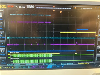
Hi, I have developed a test PCB with the DAC8741H, and am attempting to test initial communication to verify the hardware. However, I have been unable to establish SPI communication with the modem. Thus far, I have only been able to receive one sign of life from the modem (see attached scope picture) by sending [0xa4, 0xff, 0xff, 0xff, 0xff, 0xff], however no discernible messages. Any other messages I have tried get no response at all.

Note in the attached picture, C1 is Chip Select, C2 is SCLK, C3 is MOSI/SDI, and C4 is MISO/SDO

I'm testing with a Raspberry Pi 4 and the spidev library, using the xfer function to send/receive bits. I have verified that my modem is at 3.3V power, as is the logic level, and the pi is sending over MOSI to SDI, just not receiving anything.

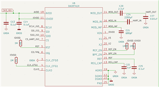
I've attached my schematic for reference.

Any advice would be appreciated, as I am not sure how to proceed. If there are any bit sequences with known responses that could be provided, or any recommendations on where to test for chip issues, that would be great.

-Libby Albanese

  • Update: by using readbytes and writebytes in the spidev library, I was able to get an echoed response (see scope photo). However, I'm still unsure exactly what messages to be sending to get responses, so any clarification on that would be appreciated

    .

  • Libby,

    Just to check can you first read back the Control register? I just want to see if the SPI is working. The register is 2h and the reset value is 0x8042. It's a good place to start to verify communications.

    After that, we can check on the modem. You can first verify that there is some sort of carrier detect from the modem itself, and then just verify the data going into it looking at the sinusoid (I assume you're looking at a HART signal).

    Joseph Wu

  • To clarify, what bit values do I send to read that register?  I think that is where part of my confusion is.

  • Libby, 

    The register address is 02, so for the read from that address, you would insert a 1 into the MSB of the communication, so the read would be 82 00 00 (the extra two bytes complete the SPI frame. 

    After that you need to send NOP frame (00 00 00) to clock out the data from the read.

    Joseph Wu

  • Hi Joseph,

    I sent [0x82, 0x00, 0x00] and got back the result (130,128,66)

  • Libby,

    Sorry, I accidentally clicked the TI thinks the problem is resolved button.

    So the read seems right. The readback is 82 80 42.

    For the modem, what are you sending? and are you able to read anything back.

    Joseph Wu

  • I have not yet tried connecting a HART device, I've just been verifying that SPI communication is working.

  • Libby,

    Ok, again the read seems correct. That value matches the default reading of the 02 register: 

    If you want, you can make another change by writing to the device. I'd try writing to the same register. Again, the control register bits are set to 80 42 as a default value. You could write to the WDTO bits (without turning on the WDT). Those bits are the upper three MSB. You can change them to 111 by writing 02 E0 42.

    Once you write these values to the device, you can check to see if the data is truly written into the register. Just read back the register to see that the value has been updated.

    Joseph Wu