This thread has been locked.
If you have a related question, please click the "Ask a related question" button in the top right corner. The newly created question will be automatically linked to this question.
1
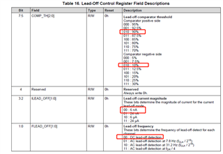
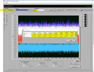
The power offset and noise of 1299 are relatively large, and the offset of 8 channels is different. Why do they have different bias problems
Is there any way to improve bias and reduce noise
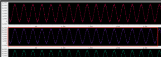
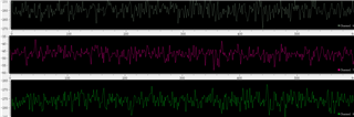
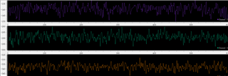
Test the short circuit and internal noise. When the conversion rate is 250 SPS.
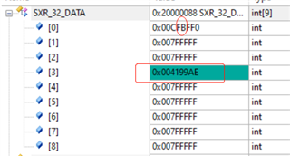
The relevant AD values are as follows. The noise is about ten microvolts. The channels with different bias are different. Some channels are 25uV and some are about 150uV
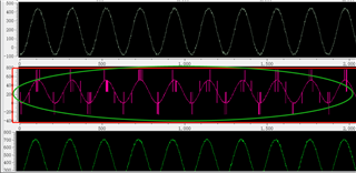
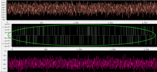
When the conversion rate is 4K SPS
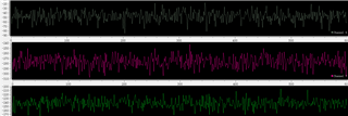
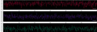
64-pin grounding and floating, this problem has not been improved.
PCB wiring is separated from analog and digital parts.
2
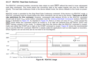
When the rotational speed is configured as 16K SPS, the data cannot be read completely,
Whether the internal clock can only be configured as 8K SPS
To configure as a 16K SPS, use an external clock to increase the frequency?
Hi,
Do you have ADS1299 evaluation kit/board(evm)?
Please use ADS1299 evaluation kit/board evm to compare&validate the noises seen in your system.
-------------------------
Noises could come from many variety of sources, power supplies, PCBA components/design/layout, cables/wires, UUT(unit under test)/UUM(unit under measure).
Pease check the Vref and AVDD to make sure they are clean.
------------------------------------------------------------------
What do you mean by " rotational speed"? and What do you mean by " the data cannot be read completely,"?
-----------------------------------------------
It's highly suggested to use ADS1299 evaluation kit/board(EVM) to co-validate/verify with your designs&configurations as well as SPI communication.
Thanks
HI,
1
Can you use your DEMO board to verify the noise and bias conditions when the speed rate is different? What might be the reason for different channel biases? Please help confirm.
2
The conversion rate here is: output data rate. When configured to 16K SPS, only 26 bytes of data can be read out completely. You can refer to the oscilloscope diagram above. Please confirm whether you can read out 27 bytes of data completely when your DEMO is configured to 16K SPS, and give the waveforms of SLCK and DRDY
Hi,
1. Noises should be different when ODR change as per datasheet -
The noise measurement results can be referred to Section 8 Parametric Measurement Information and there are Table 1 to 4 to show how noise could change when data rate change as the decimation filter bandwidth change per Figure 29 and 30.
2. "16K SPS, only 26 bytes of data can be read out completely."
May I ask do you use RDATAC or RDATA? does your host/master wait long enough(e.g. 1 Second to be able to receive 16K data samples) and have enough buffer for the data?
Thanks
HI,
Can you use your DEMO to verify the above two problems and give the waveform?
In addition, whether the common-mode feedback output needs to be amplified for better effect, because the effect of direct BIAS output is very poor now
Hi,
Demo board won't exhibit exactly the same as the noise data in the data sheet.
It's suggested to use BIASOUT and customer will need to tune the related R, C and the BIASPx and BIASNx based on the product design an through experiment&tests&data collection&analysis&V&V.
Thanks
Does your host/master continue reading for 1 second?
Do you have evaluation kit/board(EVM)? It's suggested to use EVM to verify the communication protocol and signal.
Thanks
HI,
We bought several ADS1299 chips for testing, but did not use your EVM for testing. Can you help us apply for EVM testing and return the EVM board after verification。
Make sure you reset the ADS1299 first before continue the experiment.
What was your gain settings?
-------------------------------------------------------------
Does your host/master continue reading for 1 second?
It's suggested to use EVM to verify the communication protocol and signal.
-----------------------------------
I will take a look of the following on EVM-
1. baseline DC offset and noise floor when inputs pins are internal short.
2. use 16K SPS Output Data Rate(ODR) to stream the data.
I will get back to you before 3/14.
HI,
The following problem was found regarding electrode detachment detection: different thresholds were configured, channel 3 could not be detected at all, after disconnecting all electrodes, other electrodes had no AD value change, but channel 3 still had AD data fluctuation. No short circuit problem was found in hardware testing, and all channels were normal when testing signal generator.
Help analyze the possible causes and improvement measures.
Hi,
Ok, you are using one of the datasheet page 31 Figure 36 DC Lead-Off excitation options. May I ask do you use a) or b) or c)?
It seems noises and interferences from environment, please check the power source(s), cables(length, shielding, material), grounding(common ground, any ground loop) and electrode/patch contacts.
What is your Unit Under Test(UUT)? Have you tried it with an ECG/EEG simulator?
Do you use BIASOUT? If not, could you try use BIASOUT?
and you may want to try different current and threshold settings as the impedance for some particular electrodes/nodes/location might be different.
--------------------------------------------------------------------------------------------------------
It's highly recommended to use an ADS1299EVM with an ECG/EEG simulator to test first.
Thanks
Whether the above two parts have been tested and whether there are relevant test data or waveforms?
Our scalp is connected to the human body for testing.
Two ICs have been tested, one can be detected by all channels, and the other can only be detected by channel 3 (AD value can be tested normally). It may be that the chip detection function is abnormal. Analyze the possible causes of the defect.
In addition, we found that some channels would have abnormal data or waveform and poor contact, whether the internal switch had poor contact or other possibilities, how long it was used in the 1299 market, how much it was used, and whether other customers reported the same problems.
Bad channel data is as follows:
Hi,
I need more time to look at your case, will get back to you before 2/17.
Thanks
hi,
Please see baseline noise floor when all(8) channels are shorted and Output Data Rate(ODR)=16k SPS-
And, it can stream data at ODR=16k SPS without error or data drop, see x-axis, 32000 data collected for around 2 seconds
and data can be output&saved correctly-
8 channels shorted 16kSPS.txt2260.Device_0_Volts.xls
---------------------------------------
It's suggested to use EVM with an ECG simulator as primary reference and help during evaluation and R&D.
Thanks