Other Parts Discussed in Thread: ADC3683, ADS54J69
Hi Team,
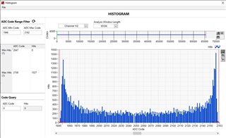
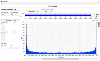
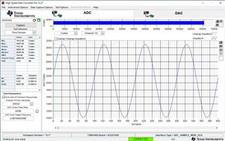
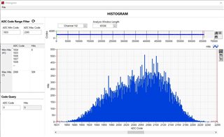
I'm using an ADC with part number: ADS5404IZAY and interfacing the LVDS output with a Xilinx Zyn Ultrascale FPGA. The ADC board we designed has been interfaced with the FPGA board using FMC connector but due to some unknown reasons, I'm getting a periodic distortion with a pattern when the ADC LVDS output data collected is converted to a histogram. I suspect, this distortion is coming somewhere from the ADC within, could you help me troubleshoot this issue? Has something like this been observed before?
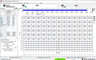
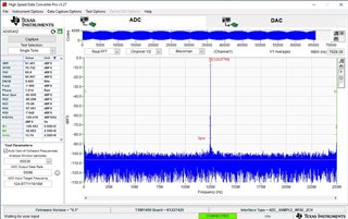
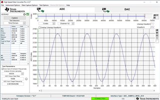
I'm attaching a document that contains a few screenshots of the experimental tests that we have ran using a signal generator output as the input to the ADS5404IZAY ADC system channel B (SECTION A: EXPERIMENTS DONE) along with some circuitry related to the ADC. The LVDS data is collected using FPGA.
ADC_ADS5404_debuggin inputs.pdf
Moreover, to give you a context, I'm sharing some major details related to the system here;
1)The differential input PCB tracks of the ADC are 100E impedance controlled. The LVDS output channels are also 100E impedance controlled.
2)ADC operation under 500MSPS.
3)There is an ADC driver with a filter just before the differential input of the ADC channel B. (SECTION C: ADC INPUT DIFFERENTIAL DRIVER CIRCUIT in the document).
4)A clock generator chip with part number: "RC32504A" has been used for providing the high-speed clock signal input to the ADC (SECTION D: ADC CLOCK GENERATOR CIRCUIT in the document))
5)Switching regulators have been used on the board but there's always a high PSRR, low noise LDO before the ADC power supplies.
6)The entire circuit board has a single common ground.
Let me know if there are any additional information required.