This thread has been locked.

If you have a related question, please click the "Ask a related question" button in the top right corner. The newly created question will be automatically linked to this question.

ADS7953-Q1: How to initialization?

Part Number: ADS7953-Q1


Hi Expert

form below example:

ADS7953: ADS7953 SPI Auto-1 mode Configure - Data converters forum - Data converters - TI E2E support forums

the first step configure GPIO but in DS, power on step auto 1 programmable resistor is in front of GPIO as below:

How to understand it?

Question 2:

0x2841: how to understand this value? Does is from below table:

but 2841: 0010 1000 0100 0001: why DI0 is 1? how to understand it?

Question 3:

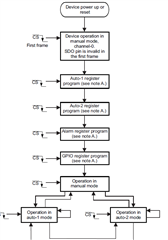
as below flowchart: device how to achieve step 1:"Program auto 1 register?" I don't know device how to know yes or no? though read back D15~12?

question 4:

customer used this device in BMS but in some power on environment that include many interference signal lead to CS frame one bit turn over.

in this condition, wrong device will lead to three wrong result:

1.    Initial configuration failed

2.  All channels sampled at reduced frequency

3. Sampled values doubled for all ADC channels

So how to avoid this wrong turn over? how to check device whether configure successfully? 

  • Hi Meng,

    Please review this forum post, since it was essentially the exact question you provided above.

    https://e2e.ti.com/support/data-converters-group/data-converters/f/data-converters-forum/1208520/ads7953-unable-to-read-out-an-ads7953-with-a-stm32f072-altough-it-should-work-in-theory/4566749#4566749

    So here are some answers to your queries:

    Q1. Please use the flow chart from section 8.4.4 on page 29, or review the flow chart from the commercial version of the device.  In the commercial datasheet, I think its a little easier to follow the sequence.  In the first frame, you must first transmit 0x8000 to enter Auto-1 programming sequence.  The second frame sets the channels you wish to include in the Auto 1 sequence, so transmitting 0xFFFF selects all 16 channels.

    Q2. See Table 2, page 30.  The 0x2841 command sets bits 13, 11, 6 and 0 in the mode control register.  Bit 13 selects the register and bit 11 allows programming of bits 10 thru 0.  Bit 6 sets the range to 2xVref and bit 0 sets GPIO0 output to 'logic one'.

    Q3. The 'yes' or 'no' decision in the flow chart is not a decision the device makes - that is Operator Choice as in "Do you wish to Program the auto 1 register?"  If yes, transmit 0x8000 .  This is an error in the datasheet and will be fixed.  There is no command available to read back the register contents.

    Q4. Feel free to provide a schematic and layout and we can take a look to see what might help reduce noise in the system.  As noted in Q3 response, there is no means to read back the configuration registers.