A related question is a question created from another question. When the related question is created, it will be automatically linked to the original question.
If you have a related question, please click the "Ask a related question" button in the top right corner. The newly created question will be automatically linked to this question.
I am sorry that I do not have a ready code to share with you, but this device is fairly easy to configure.
Fig 52 of the ADS7953 datasheet describes the steps involved in programming the device for Auto-1 Channel-sequencing mode.
Let us assume that the customer is interested in configuring the device to capture data from Channels 1,3 and 5, in Range 2 and with GPIO0 as output high
Here is the sequence of commands to send over the SDO to configure the device:
>> wr 0x4200 // Device resets all registers in the next CS frame to the reset states (it also resets itself).
>> wr 0x4001 // Configure GPIO0 as a general purpose output
>> wr 0x8000 // Program Register for Auto-1 Frame 1
>> wr 0x002A // Program Register for Auto-1 Frame 2, to select channels Ch1,Ch3 and Ch5
>> wr 0x2C40 // Enable Auto-1 Mode, counter set to lower programmed channel (Ch1), Select Range 2 operation
>> wr 0x2841 // Stay in Auto-1 Mode, enable increment counter, Range 2 operation and GPIO set as output high
The device is now configured and these setting can be retained by driving SDI low. The channel selection will cycle through the 3 channels with each subsequent frame.
Hope this helps. Do let me know if you need any clarifications on this.
You could stay in a given mode by either reprogramming the bits for that mode in every frame or by writing 0x0000 as mentioned in Table 7. By "driving SDI low" I meant writing 0x0000 for no change, as you have correctly mentioned.
The 0x4200 ensure that all the device registers are reset after power-up and 0x2840 since you do not want to use the GPIOs.
Please try this sequence. If this does not work we will have to look at the circuit design and timing more closely.
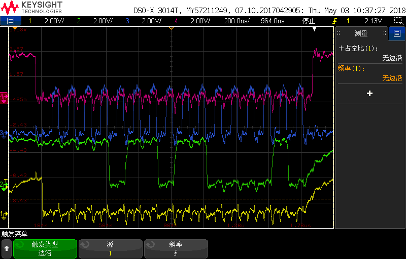
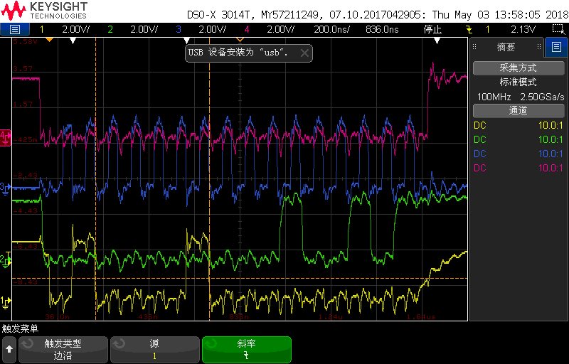
1. Since you are writing 0x0000, the timing of SDI with respect to the SCLK is not clear in your screen capture. Could you please share a screenshot when writing 0x4200?
2. Could you share a circuit schematics for the section of the design related to the ADS7953